EasyManua.ls Logo

JVC KD-R430J - User Manual

JVC KD-R430J
16 pages
Print Icon
To Next Page IconTo Next Page
Loading...
SERVICE MANUAL
COPYRIGHT © 2012 JVC KENWOOD Corporation
No.MA503<Rev.003>
2012/4
CD RECEIVER
MA503<Rev.003>20124SERVICE MANUAL
KD-R430J, KD-R431E, KD-R431EN, KD-R431EU,
KD-R431EY, KD-R432E, KD-R432EN, KD-R432EU,
KD-R432EY, KD-R434UI, KD-R435U, KD-R435UN,
KD-R436U, KD-R436UN, KD-R436UP,
KD-R437EE, KD-R439UR, KD-R48EE, KD-R531E,
KD-R531EN, KD-R531EU, KD-R531EY, KD-R54J
COPYRIGHT © 2012 JVC KENWOOD Corporation
Lead free solder used in the board (material : Sn-Ag-Cu, melting point : 219 Centigrade)
Lead free solder used in the board (material : Sn-Cu, melting point : 230 Centigrade)
DETACH PANEL
KD-R430J
KD-R431E
KD-R431EN
KD-R431EU
KD-R431EY
KD-R432E
KD-R432EN
KD-R432EU
KD-R432EY
KD-R434UI
KD-R435U
KD-R435UN
KD-R436U
KD-R436UN
KD-R436UP
KD-R437EE
KD-R438J
KD-R438UF
KD-R48EE
KD-R531E
KD-R531EN
KD-R531EU
KD-R531EY
KD-R54J
CP-R430JD
CP-R431ED
CP-R431ED
CP-R431ED
CP-R431ED
CP-R432ED
CP-R432ED
CP-R432ED
CP-R432ED
CP-R434UID
CP-R435UD
CP-R435UD
CP-R436UD
CP-R436UD
CP-R436UD
CP-R437EED
CP-R438JD
CP-R438UFD
CP-R48EED
CP-R531ED
CP-R531ED
CP-R531ED
CP-R531ED
CP-R54JD
Model Parts number
For KD-R430,KD-R431,
KD-R432,KD-R435,KD-R436,
KD-R437,KD-R48,KD-R531,
KD-R54
For
KD-R430, KD-R434,
KD-R435, KD-R435,
KD-R436, KD-R436,
KD-R436, KD-R439,
KD-R54
For KD-R430,KD-R54
For
KD-R531,KD-R432,KD-R431
Question and Answer IconNeed help?

Do you have a question about the JVC KD-R430J and is the answer not in the manual?

JVC KD-R430J Specifications

General IconGeneral
BrandJVC
ModelKD-R430J
CategoryCar Receiver
LanguageEnglish

Summary

Model Identification and Panel Detachment

US Model Specifications

Audio Amplifier Specifications (US)

Details of audio output, impedance, and frequency response for US models.

Tuner Section Specifications (US)

FM/AM frequency ranges, sensitivity, and stereo separation for US models.

CD Player and USB Section Specs (US)

Covers CD signal detection, channels, and USB standards for US models.

General Unit Specifications (US)

Power requirements, dimensions, and mass for US models.

Safety Precautions and Component Handling

General Safety and Repair Guidelines

Essential safety rules, warnings, cautions, and handling of critical parts.

Leakage Shock Hazard Testing Procedures

Methods for testing leakage current on exposed metal parts for safety.

ESD Prevention and Traverse Unit Care

Preventing Static Electricity Damage

Procedures to prevent ESD damage to optical pickups, including grounding.

Traverse Unit and Optical Pickup Handling

Guidelines for handling the sensitive traverse unit and optical pickup during service.

Traverse Unit Decomposition Notes

Specific instructions for disassembling and reassembling the traverse unit.

Laser Product Safety and Label Information

Laser Radiation Classification and Warnings

Details on Class 1M laser radiation, safety cautions, and operating procedures.

Label Reproduction and Position Guidelines

Information on the placement and reproduction of warning labels on the product.

Main Unit Disassembly Procedures

Bottom Chassis and Front Chassis Removal

Steps for detaching the bottom and front chassis sections of the main unit.

Removing the Electric Unit Assembly

Instructions for detaching the main electric unit from the chassis.

CD Mechanism Component Disassembly

CD Mechanism and Switch Unit Removal

Steps for removing the CD mechanism and the switch unit from the main assembly.

Mecha Control Board Removal Process

Detailed steps for removing the mecha control board from the CD mechanism.

CD Mechanism Sub-Assembly Removal

Traverse Mechanism and Pickup Unit Removal

Procedures for detaching the traverse mechanism and the pickup unit.

Spindle Motor Removal Steps

Instructions for removing the spindle motor from the CD mechanism assembly.

Loading Motor Assembly Removal

Loading Motor Component Detachment

Steps to remove the loading motor assembly and associated parts.

System Adjustment and Test Modes

Service Test Mode Operation

How to enter and operate the service test mode for system diagnostics.

Common Operation Mode Functions

Details on common operations available across different sources within the test mode.

CD Error Information Display Modes

Mecha and Load;Eject Error Logs

How to view mechanical and loading/eject error history for the CD mechanism.

CD Time Code Error Count Display

Information on displaying and interpreting CD time code error counts.

DC Error Detection and Information

DC Error Information Mode

Entering and viewing DC error detection status and information.

DC Error Mode Operation Specs

Specifications for operating the DC error detection modes and clearing data.

DC Offset Error Analysis and Resolution

DC Offset Detection Circuit Design

Explanation of the circuit design for detecting DC offset at speaker outputs.

Causes and Checking of DC Offset

Identifying potential causes and methods for checking DC offset errors.

DC Offset Timing and Error Handling

Understanding detection timing and procedures for handling/clearing DC offset errors.
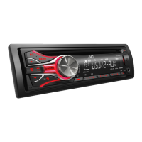
Related product manuals