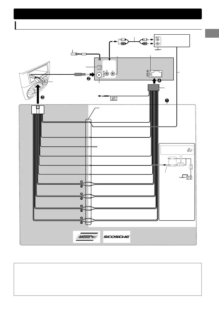
Wiring connection
MIC
Metra Electronics: www.metraonline.com
Scosche Industries: www.scosche.com
Rear/subwoofer
output
Join the same color wires
together.
For more information:
(separately purchased)
Vehicle-specific Wiring Harness
Make this connection
if your vehicle factory
wiring harness does
not have “12 V
ignition switch” wire.
Separate
red wire
Fuse block
Ignition switch
(not used) *
2
Telephone muting
Purple/black
Purple: Rear speaker (right)
Green/black
Green: Rear speaker (left)
Gray/black
Gray: Front speaker (right)
White/black
White: Front speaker (left)
Black: Ground
Red: 12 V Ignition switch
Yellow: 12 V Battery
Orange/white: Illumination
Blue/white: To amplifier
Blue/white:
Remote (200 mA max.)
Blue: To power antenna
Recommended
connection
Light blue/yellow
Antenna terminal
To the steering wheel
remote control adapter
Factory wiring
harness (vehicle)
Rear ground terminal
Remote
wire*
1
MIC (Microphone input terminal) (A page 11)
10 A fuse
JVC Amplifier
Signal cord*
1
D
*1 Not supplied for this unit.
*2 Insulate to prevent short circuit.
If you have any troubles, try the following:
1
Check “Troubleshooting” (' page 26).
2
Reset the unit. (' page 3)
3
Contact (USA only)
Call: 1-800-252-5722 ( or ) visit: http://www.jvc.com
Installation/Connection
ENGLISHޓ|
31
2012/11/22ޓ10:10:26KD-X250BT_J_EN
 Loading...