KS-AX4700
1-5
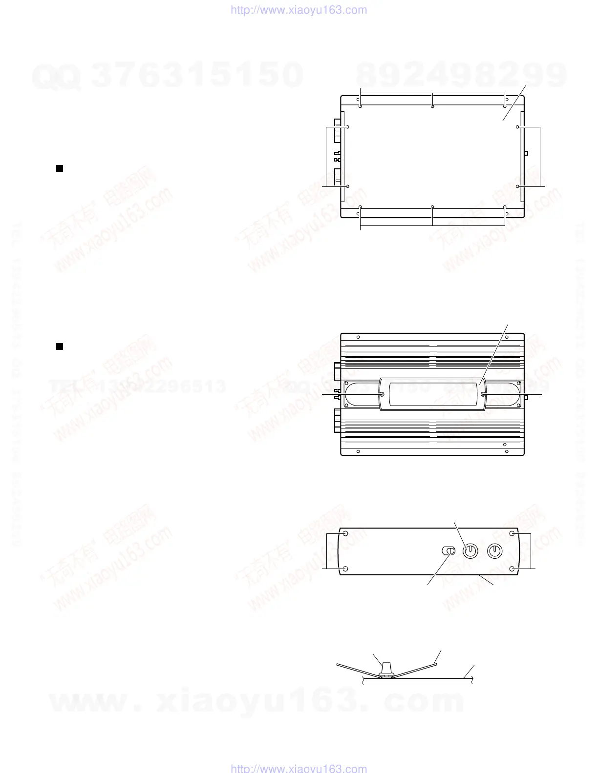
From the bottom side of the main unit, remove the 4
screws A retaining the bottom cover.
Then remove the 6 screws B retaining the bottom
cover.
Remove the bottom cover.
1.
2.
3.
Removal of main parts
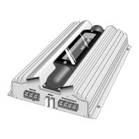
Removing the bottom cover (see Fig. 1)
Remove the bottom cover from the main unit.
Loosen and remove the 2 screws C retaining the top
plate on the main unit. (Stoppers are attached to the
backs of the C screws so that they cannot be
removed easily.)
1.
2.
Remove the 6 volume knobs on top of the control
panel. If it cannot be pulled out easily, insert a rope
or wire between the base of the volume knob and the
control panel so that the volume knob is raised a little
above the surface and then remove it.
(Be careful when inserting a lever etc. not to
scratch the surface of the control panel).
Remove the 4 screws D retaining the control panel.
Then detach the control panel and the switch knobs.
3.
4.
Removing the MAIN PCB
(see Fig. 2 to 8)
(Side view)
Rope or wire
Volume knob
Control panel
Bottom cover
Fig. 1
Fig. 3
Fig. 2
Fig. 4
If electricity is connected during disassembly,
it must be a no load current. If it is load
current, be sure to attach a heat sink to the
power-amp IC. This will be damaged if the
above precautions are not followed, as it
does not have a sub heat sink attached to it.
CAUTION:
A
B
A
B
Top panel
C
C
Switch knob
Control panel
D D
Volume knob
w
w
w
.
x
i
a
o
y
u
1
6
3
.
c
o
m
Q
Q
3
7
6
3
1
5
1
5
0
9
9
2
8
9
4
2
9
8
T
E
L
1
3
9
4
2
2
9
6
5
1
3
9
9
2
8
9
4
2
9
8
0
5
1
5
1
3
6
7
3
Q
Q
TEL 13942296513 QQ 376315150 892498299
TEL 13942296513 QQ 376315150 892498299
http://www.xiaoyu163.com
http://www.xiaoyu163.com
 Loading...