2-5
KS-F150
KS-FX12
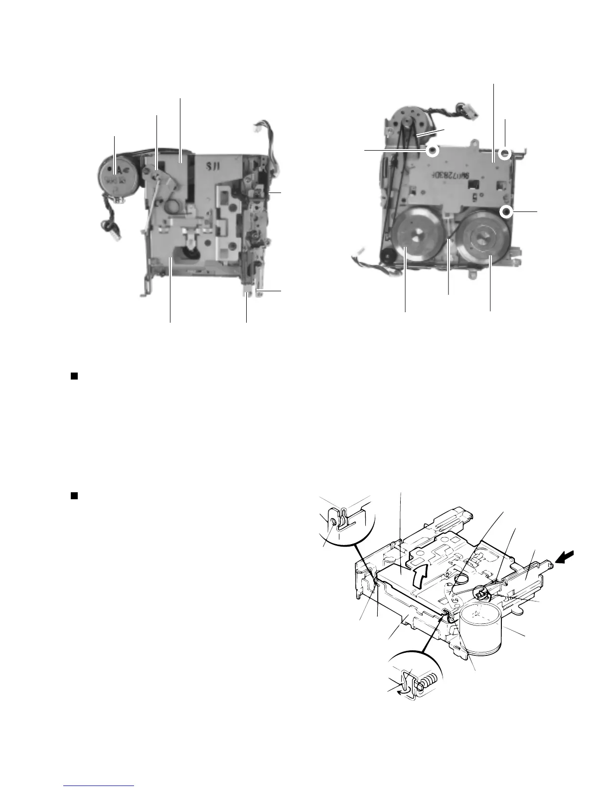
<Cassette Mechanism Sections>
Direction
switch board
Motor assembly
Cassette hanger
Center plate
Cassette holder
REW Lever
FF Lever
Fig. 1
Main belt
Sub-belt
Reel base assembly
Flywheel
assembly(B)
Flywheel
assembly(F)
Fig. 2
7
8
7
Removing the Main Parts of Cassette Mechanism
1. Remove the cassette hanger and FF, REW, EJECT lever etc. , when you need to replace or adjusting head.
2. The main belt can be replaced directly.
3. To change the sub-belt, remove the three screws ( 7 ) and loosen one screw ( 8 ).
Then raise the belt side of the reel base assembly slightly.
Fig. 3
To see
Fig.5
Cassette hanger
Center plate
Return link
EJECT lever
Chassis
Claw
Claw
a
a
b
b
b
Removing the Cassette Hanger
( See Fig.1 and 5 )
1. From the rear of the unit, bend the cassette
hanger and chassis the five claws ( a ), ( b )
outwards.
2. While pressing the EJECT lever, remove the
cassette hanger.
3. Remove the return link from the center plate of the
cassette hanger.
 Loading...