10
2
1
3
3
4
5
2
1
ENGLISH
ELECTRICAL CONNECTIONS
To prevent short circuits, we recommend that you disconnect the
battery’s negative terminal and make all electrical connections
before installing the unit. If you are not sure how to install this unit
correctly, have it installed by a qualified technician.
Note:
This unit is designed to operate on 12 volts DC, NEGATIVE
ground electrical systems. If your vehicle does not have this
system, a voltage inverter is required, which can be purchased at
JVC car audio dealers.
• Replace the fuse with one of the specified rating. If the fuse
blows frequently, consult your JVC car audio dealer.
• If noise is a problem...
This unit incorporates a noise filter in the power circuit. However,
with some vehicles, clicking or other unwanted noise may occur.
If this happens, connect the unit’s rear ground terminal (See
connection diagram below.) to the car’s chassis using shorter
and thicker cords, such as copper braiding or gauge wire. If noise
still persists, consult your JVC car audio dealer.
• Maximum input of the speakers should be more than 40 watts at
the rear and 40 watts at the front, with an impedance of 4 to 8
ohms.
• Be sure to ground this unit to the car’s chassis.
• The heat sink becomes very hot after use. Be careful not to
touch it when removing this unit.
wÐdŽwÐdŽ
wÐdŽwÐdŽ
wÐdŽ
WOzUÐdNJ« öOu²«WOzUÐdNJ« öOu²«
WOzUÐdNJ« öOu²«WOzUÐdNJ« öOu²«
WOzUÐdNJ« öOu²«
·dÞ qBHÐ wu½ ¨WOzUÐdNJ« dz«Ëb« w dOBIð ÀËbŠ lM*
VOdð q³ WOzUÐdNJ« öOu²« qLŽ rŁ VU« W¹—UD³«
q?J?A?Ð “U?N?'« V?O?d?ð W?O?H?O?J?Ð p?²?d?F? Âb?Ž WUŠ w Æ“UN'«
q¼RË h² hA “UN'« VOdð WOKLŽ „dð vłd¹ ¨`O×
Æ…eNłô« Ác¼ q¦ VOd²
∫WEŠö∫WEŠö
∫WEŠö∫WEŠö
∫WEŠö
—UOð WDÝ«uÐ qLFO “UN'« «c¼ rL bI
dýU³ wzUÐdN dýU³ wzUÐdN
dýU³ wzUÐdN dýU³ wzUÐdN
dýU³ wzUÐdNDC
¨¨
¨¨
¨
VUÝ i¹—Qð WOzUÐdN WLE½« ¨Xu ±≤VUÝ i¹—Qð WOzUÐdN WLE½« ¨Xu ±≤
VUÝ i¹—Qð WOzUÐdN WLE½« ¨Xu ±≤VUÝ i¹—Qð WOzUÐdN WLE½« ¨Xu ±≤
VUÝ i¹—Qð WOzUÐdN WLE½« ¨Xu ±≤œułË ÂbŽ WUŠ w Æ
¨ÃU?²?u? ‰u?× Â«b²Ý« V−¹ ¨pð—UOÝ w ÂUEM« «c¼ q¦
«—U?OK WOðuB« …eNłô« ¡öË s ‰u;« «c¼ ¡«dý sJ1Ë
W—UJVCÆ
•«–« ÆW?u?u?*« U?ÝU?O?I?« f?H½ qL×¹ dšPÐ “uOH« ‰b³²Ý«
WOðuB« …eNłô« ¡öË …—UA²Ý« vłd¹ ¨“uOH« ‚«d²Š« —dJð
W—U «—UOKJVCÆ
•ÆÆÆWKJA*« u¼ ZO−C« ÊU «–«
W???U???D???« …d???z«œ q???š«œ Z???O???−???{ d???²???K??? “U??N??'« «c??¼ Âb????²????¹
Ÿu½ Àb×¹ Ê« sJ1 ¨«—UO« iFÐ w ¨p– l ÆWOzUÐdNJ«
q¦ ÀËbŠ WUŠ w Æ»užd*« dOž ZO−C« Ë« WIDID« s
i?¹—Q²« ·dÞ qË« ¨p–
“U?N?'« WOHKš w œułu*«“U?N?'« WOHKš w œułu*«
“U?N?'« WOHKš w œułu*«“U?N?'« WOHKš w œułu*«
“U?N?'« WOHKš w œułu*«d?E½«®
W??D??Ý«u??Ð …—U??O????« q??J??O??¼ l?? ©q??H??Ýô« w?? q?O?u?²?« r?Ý—
Ë« ‰Ëb:« ”U×M« pKÝ q¦ ¨pLÝ«Ë dB« „öÝ« «b²Ý«
¨Z?O?−?C?« Ë« W?I?D?I?D?« n?u?ð Âb?Ž W?UŠ w ÆwÝUOI pKÝ
W—U «—UOK WOðuB« …eNłô« ¡öË …—UA²Ý« vłd¹JVCÆ
•¥∞ s? d?¦?« U?ŽU?L??« q?šb? v?B?ô« b?(« ÊuJ¹ Ê« V−¹
l? ¨W?O?U?ô« U?ŽU?L??K? ◊«Ë ¥∞ Ë W?O?H?K?)« UŽULK ◊«Ë
5Ð WF½U2
ÆÂË« ∏ v« ¥ÆÂË« ∏ v« ¥
ÆÂË« ∏ v« ¥ÆÂË« ∏ v« ¥
ÆÂË« ∏ v« ¥
•
Æ…—UO« qJO¼ l “UN'« i¹—Qð s bQðÆ…—UO« qJO¼ l “UN'« i¹—Qð s bQð
Æ…—UO« qJO¼ l “UN'« i¹—Qð s bQðÆ…—UO« qJO¼ l “UN'« i¹—Qð s bQð
Æ…—UO« qJO¼ l “UN'« i¹—Qð s bQð
•bQð Æ«b²Ýô« bFÐ «bł WMšUÝ …—«d(« iHš W×OH `³Bð
Æ“UN'« Ÿe½ bMŽ UN²ö ÂbŽ s
A Typical Connections / /
WOł–uLM« öOu²«WOł–uLM« öOu²«
WOł–uLM« öOu²«WOł–uLM« öOu²«
WOł–uLM« öOu²«
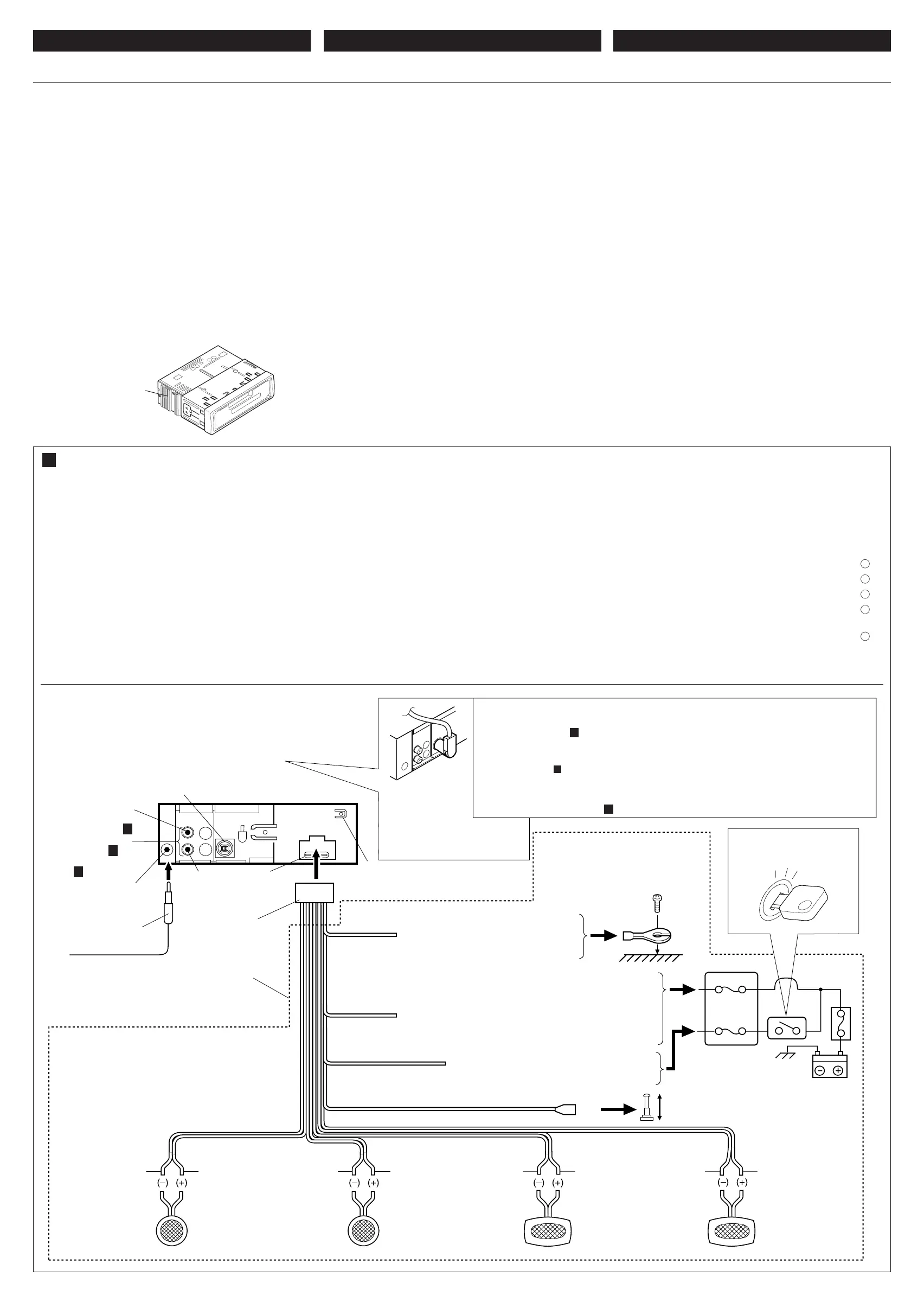
Before connecting: Check the wiring in the vehicle carefully.
Incorrect connection may cause serious damage to this unit.
1
Connect the colored leads of the power cord to the car battery,
speakers and automatic antenna (if any) in the following
sequence.
1 Black: ground
2 Yellow: to car battery (constant 12V)
3 Red: to an accessory terminal
4 Blue with white stripe: to automatic antenna (200mA
max.)
5 Others: to speakers
2
Connect the antenna cord.
3
Finally connect the wiring harness to the unit.
∫q?O?u?²?U?Ð ¡b?³« q³ ∫q?O?u?²?U?Ð ¡b?³« q³
∫q?O?u?²?U?Ð ¡b?³« q³ ∫q?O?u?²?U?Ð ¡b?³« q³
∫q?O?u?²?U?Ð ¡b?³« q³…—U?O??« w? „ö?Ýô« W?J?³ý s bQð
Ê« s?J?1 Æ“U?N?'« q?O?u?ð W?OKLŽ w QDš Àb×¹ ô v²Š WbÐ
Æ“UN−K wIOIŠ qDŽ ‰uBŠ v« ¡vÞU)« qOu²« V³¹
±±
±±
±l? W?O?zUÐdNJ« WUD« b¹Ëeð pK W½uK*« „öÝô« qË«
Ê«® w?J?O?ðU?u?ðËô« w?z«uN«Ë UŽUL« ¨…—UO« W¹—UDÐ
ÆwU²« qK²« VŠ ©błË
±©…—UO« qJO¼ l® ÷—ô« l ∫œuÝô« pK«
≤©Xu ±≤ XÐUŁ® …—UO« W¹—UDÐ l ∫dHô« pK«
≥wU{ô« ·dD« l ∫dLŠô« pK«
¥wJOðUuðËô« wz«uN« l ∫iOÐôUÐ jD<« ‚—“ô« pK«
©dO³« wKKO ≤∞∞ vBô« b(«®
µUŽUL« l ∫Èdšô« „öÝô«
≤≤
≤≤
≤Æwz«uN« pKÝ qË«
≥≥
≥≥
≥Æ“U?N'« l „öÝô« qUŠ qË« ¨«dOš«
Heat sink
iHš W×OH
…—«d(«
Green with black stripe
œuÝôUÐ jD dCš√
White with black stripe
jD iOЫ pKÝ
œuÝôUÐ
Gray
ÍœU—
White
iOÐ√
To antenna
wz«uN« v«
JVC CD changer jack
I³f ³bÒ‰ «ôÝDu«½U «*b−W
CD U—W JVC
10A fuse
Ou“ ∞± «³Od
Right
5LO«
Rear ground terminal
wHK)« i¹—Q²« ·dÞ
To metallic body or chassis of the car
…—UO« qJO¼ Ë« w½bF*« r'« v«
w½bF*«
*1: Before checking the operation of this unit prior to
installation, this lead must be connected, otherwise
power cannot be turned on.
¿
±∫V−¹ ¨VOd²« q³ “UN'« «c¼ qOGAð h× q³
ÊËbÐ “UN'« qOGAð sJ1 ô YOŠ ¨pK« «c¼ qOuð
ÆpK« qOuð
Red
dLŠ√
Blue with white stripe
iOÐôUÐ jD ‚—“« pKÝ
Purple with black stripe
œuÝôUÐ jD w½«uł—«
Right speaker (rear)
«LUŽW «OLMv ®«)KHOW©
Fuse block
“uOH« WŽuL−
To automatic antenna if any
błË Ê« wJOðUuðËô« wz«uN« v«
Left speaker (rear)
©WOHK)«® ÈdO« WŽUL«
Green
dCš«
Right speaker (front)
©WOUô«® vMLO« WŽUL«
Gray with black stripe
œuÝôUÐ jD ÍœU—
Left speaker (front)
©WOUô«® ÈdO« WŽUL«
To an accessory terminal in the fuse block
“uOH« WŽuL− w wU{ô« ·dD« v«
Yellow*
1
dH√
¿
±
Black
œuÝ√
To a live terminal in the fuse block connecting
to the car battery (bypassing the ignition switch)
«v «Dd· «(w w −LuŽW «HOu“ «*uuW
l «³DU—¹W ®dË—« 0H²UÕ «ôý²FU‰©
Ignition switch
‰UF²ýô« ÕU²H
*
*
Not included with this unit.
Ëe dOžÒÆ“UN'« «c¼ l œ
*
* Before connecting the CD changer, make sure that the unit is turned off.
When connecting a CD changer, we recommend to use one of the CH-X series CD changers.
• If your CD changer is one of the KD-MK series, you need an optional cord (KS-U15K).
You can also use an external component such as a portable MD player by connecting the Line Input Adaptor KS-U57
(not supplied) (see diagram B .)
* b³ qOuð q³Ò W?−b*« W½«uDÝô« ‰CDÆ“UN'« qOGAð ·UI¹« s bQð ¨Ò
JVC CD changer or
another external
component
b³Ò W−b W½«uDÝ« ‰CDW—U
JVCdš« wł—Uš X½U½u³L “UNł Ë«
!"#$%&'()*+,#-./0123#4567/
!"#$%&'()*$+,)-./012345678
!"#$
!"#$%12V !"#$%&' !"#$%&
!"#$%&'( )*+,$-./JVC !"#
!"
• !"#$%&'()* !+,- !./0123
JVC !"#$%&'
• !"#$
!"#$%&'()*+,-./01 2345617
!"#$%&'()*+,-./012345678
!"#$%&'()*+&,-./0'123 !
!"#$%&'( !"#$%&'()*+ JVC
!"#$%&'
• !"#$%&'()*%+ 40 !"#$%&'(
40 !"#$ 4 – 8
• !"#$%&'()
• !"#$%&'(%)*+#,-./#01234
!"
!"#$
! !"#$%&'()*+%,&-./01234
1
!"#$%&'()*+,-.%/012/34
!"#$%&' !"#
1 !"
2 !"#$%& 12V
3 !"#$%&'()*+,-
4 !"#$%&'()*+,- 200
5 !"#$%
2
!" #$%&'
3
!"#$%&'&()*+,
!"#$
!"#$
!"#$%
!"#$%&'
!"#$%&'()*+ !"#$,
!"#$ !"#$%&'
!"#$%&'()*
!
!"
!"#$%
! !
!"#$
! !
!"#$
! !
!
!
10A
!"#$%
*1: !"#$%&'()*+,-.$/01234
!"#$%&'(
*1
!"#$
! !
JVC CD !"
JVC CD !
!"#
!
!
!
CD !"#$%&'()*+
!"#$ ! CH-X CD !
!CD !KD-MK !"#$ KS-U15K
!"#$%&'()*KS-U57 !"#$%&'()*+,
MD !"# B
*
jD<« dE½«®B©
W−b*« U½«uDÝô« ôb³ bŠ« qOu²Ð wu½CD WKKÝ s CH-XÆ
•«–« UÊ ³bÒ‰ «ôÝDu«½U «*b−W CD «cÍ 9²KJW s ÝKKW KD-MK¨ Ýu· %²UÃ «v ÝKp «{Uw ®KS-U15K©Æ
b?³ q¦ wł—Uš X½U½u³L “UNł ‰ULF²Ý« UC¹« pMJ1Ò W½«uDÝ« ‰MD¡v?¹UN qOu²Ð p–Ë p¹œ wMO*«
j)« qšœKS-U57Ëe dOž® Ò wDOD²« rÝd« dD½«® ©“UN'« «c¼ l œ
B
©Æ
Left
—UO«
Line out
(see diagram B )
j)« Ãdš
wz«uN« ·dÞ
Antenna terminal
Purple
w½«uł—«
B
•
•
•
•
•
•
Install.KS-FX250[U]/f 02/14/2000, 1:56 PM3
 Loading...