1-8 (No.MA235)
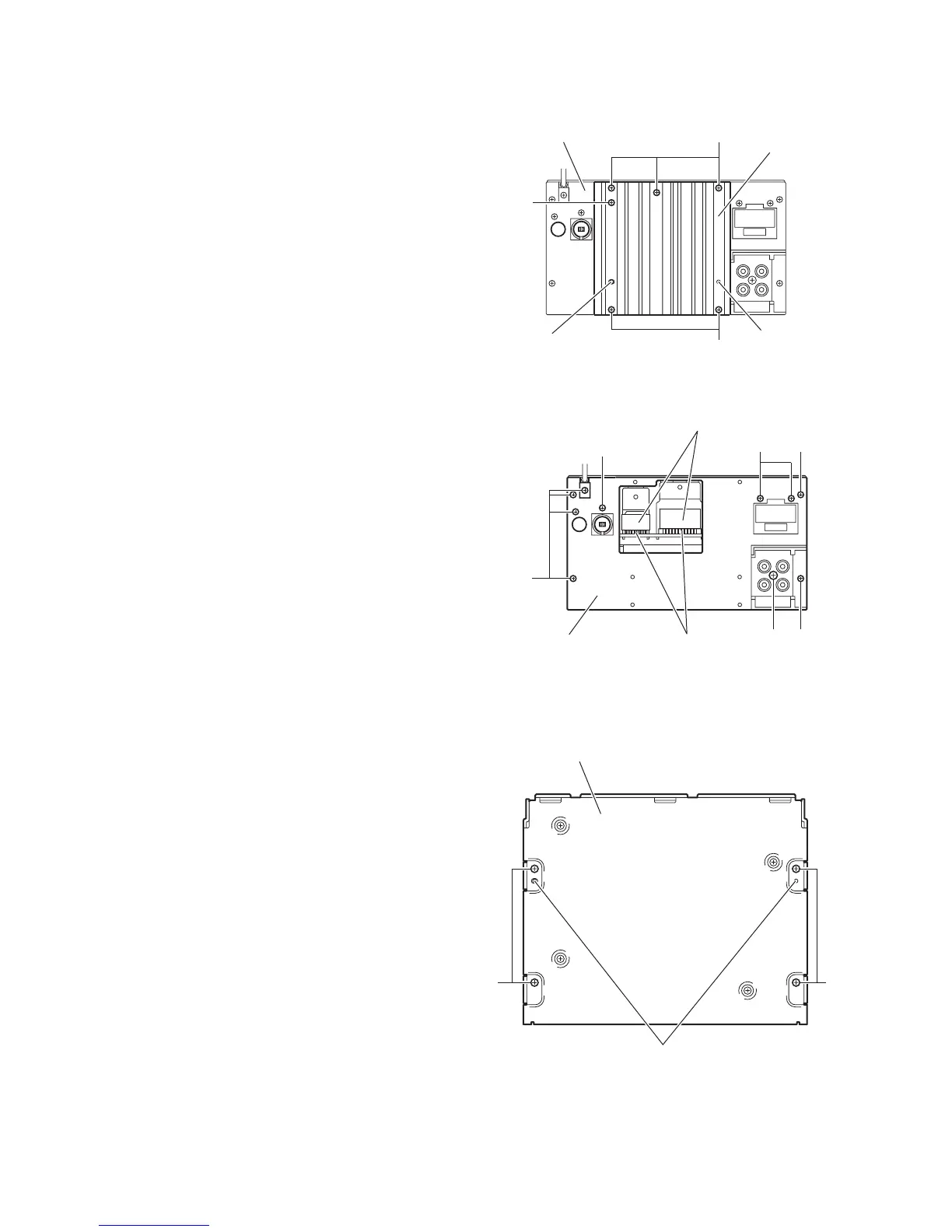
3.1.2 Removing the heat sink
(See Figs.3 and 4)
(1) From the back side of the main body, remove the six
screws B attaching the heat sink. (See Fig.3.)
(2) Remove the heat sink from the main body.
Note:
• Before attaching the heat sink, attach the cooling rubbers on
the power amplifier IC. (See Fig.4)
• When attaching the heat sink, set the projections b on the
rear bracket in the holes of the heat sink. (See Fig.3.)
3.1.3 Removing the rear bracket
(See Fig.4)
• Remove the heat sink.
(1) From the back side of the main body, remove the seven
screws C, two screws D and screw E attaching the rear
bracket.
(2) Remove the rear bracket from the main body.
Fig.3
Fig.4
3.1.4 Removing the bottom chassis assembly
(See Fig.5)
• Remove the front panel assembly, heat sink and rear bracket.
(1) From the bottom side of the main body, remove the four
screws F attaching the bottom chassis assembly.
(2) Take out the bottom chassis assembly from the main body.
Reference:
When attaching the bottom chassis assembly, set the projec-
tions c of the main body in the holes of the bottom chassis as-
sembly.
Fig.5
B
B
B
bb
Rear bracket
Heat sink
CD
C
E
C
C
Rear bracket
Cooling rubbers
Power amplifier IC
Bottom chassis assembly
c
FF
 Loading...