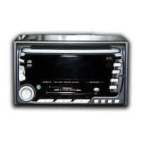
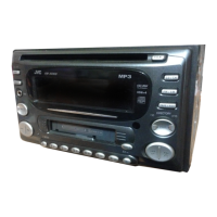
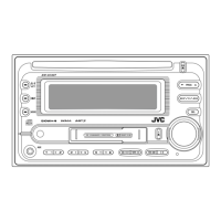
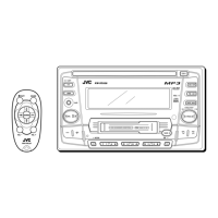
KW-XC777
1-34
1.Pin layout
1
~
30
80
~
51
100 ~ 81
31 ~ 50
2.Pin function (1/2)
Pin No.
1
2
3
4
5
6
7
8
9
10
11
12
13
14
15
16
17
18
19
20
21
22
23
24
25
26
27
28
29
30
31
32
33
34
35
36
37
38
39
40
41
42
43
44
45
I/O
-
-
-
-
-
-
-
-
-
-
-
-
-
-
I
I
I
I
I
I
I
O
-
-
I
I
I
I
I
I
I
I
-
I
O
-
I
O
I/O
O
O
O
O
O
O
Function
Non connect
Non connect
Non connect
Non connect
Non connect
Non connect
Non connect
Mute output terminal L:mute
Connect to VDD
Connect to 12.5MHz X'tal oscillator (output) (Main)
Connect to 12.5MHz X'tal oscillator (input) (Main)
Connect to GND
Connect to 32.768KHz X'tal oscillator (output) (Sub)
Connect to 32.768KHz X'tal oscillator (Input) (Sub)
System reset input terminal
Interlupt signal detection terminal from J-BUS comunication
Interlupt signal detection terminal from remote controller
ACC power supply detection terminal ("L" input hold)
Backup power supply detection terminal
CD mechanism SW1 input terminal
Cassette mech power supply inclease request signal input
Audio signal switching output (CD-CH/LINE INPUT mode:"H")
Connect to VDD (A/D converter power supply)
Connect to VDD (A/D converter reference power supply)
KEY0 input terminal
KEY1 input terminal
KEY2 input terminal
KEY3 input terminal
S meter voltage input terminal
Level meter level input terminal
Power supply input terminal from thermister (for contrast temp.)
Pickup laser level detection terminal
Connect to GND (A/D converter, D/A converter GND)
Dimmer signal input terminal (dimmer "L" input)
DIMMER ON "H" output
Connect to VDD (D/A converter reference power supply)
Data input from J-BUS
Data output of J-BUS
Clock output for J-BUS
Input/output select signal outtput of J-BUS (output "H", input "L")
Data output terminal for LCD driver
Clock output terminal for LCD driver
Chip enable output terminal for LCD driver
BEEP output terminal (output frequency 1.5KHz,3.1KHz)
Non connect
Symbol
NC
NC
NC
NC
NC
NC
NC
MUTE
VDD
X2
X1
GND
XT2
XT1
RESET
J-BUS INT
REMOCOM
ACC DET
MEMOREY DET
SW1
CST P.REQ
AD SEL
AVDD
AVREF0
KEY0
KEY 1
KEY 2
KEY 3
S METER
ANA
TEMP
IOP
AVss
DIMMER IN
CFL BRIGHT
AVREF1
J-BUS SI
J-BUS SO
J-BUS SCK
J-BUS I/O
LCD DATA
LCD SCK
LCD CE
BEEP
NC
UPD784216AGC160 (IC701) : CPU
w
w
w
.
x
i
a
o
y
u
1
6
3
.
c
o
m
Q
Q
3
7
6
3
1
5
1
5
0
9
9
2
8
9
4
2
9
8
T
E
L
1
3
9
4
2
2
9
6
5
1
3
9
9
2
8
9
4
2
9
8
0
5
1
5
1
3
6
7
3
Q
Q
TEL 13942296513 QQ 376315150 892498299
TEL 13942296513 QQ 376315150 892498299
http://www.xiaoyu163.com
http://www.xiaoyu163.com

 Loading...