(No.YA408)1-15
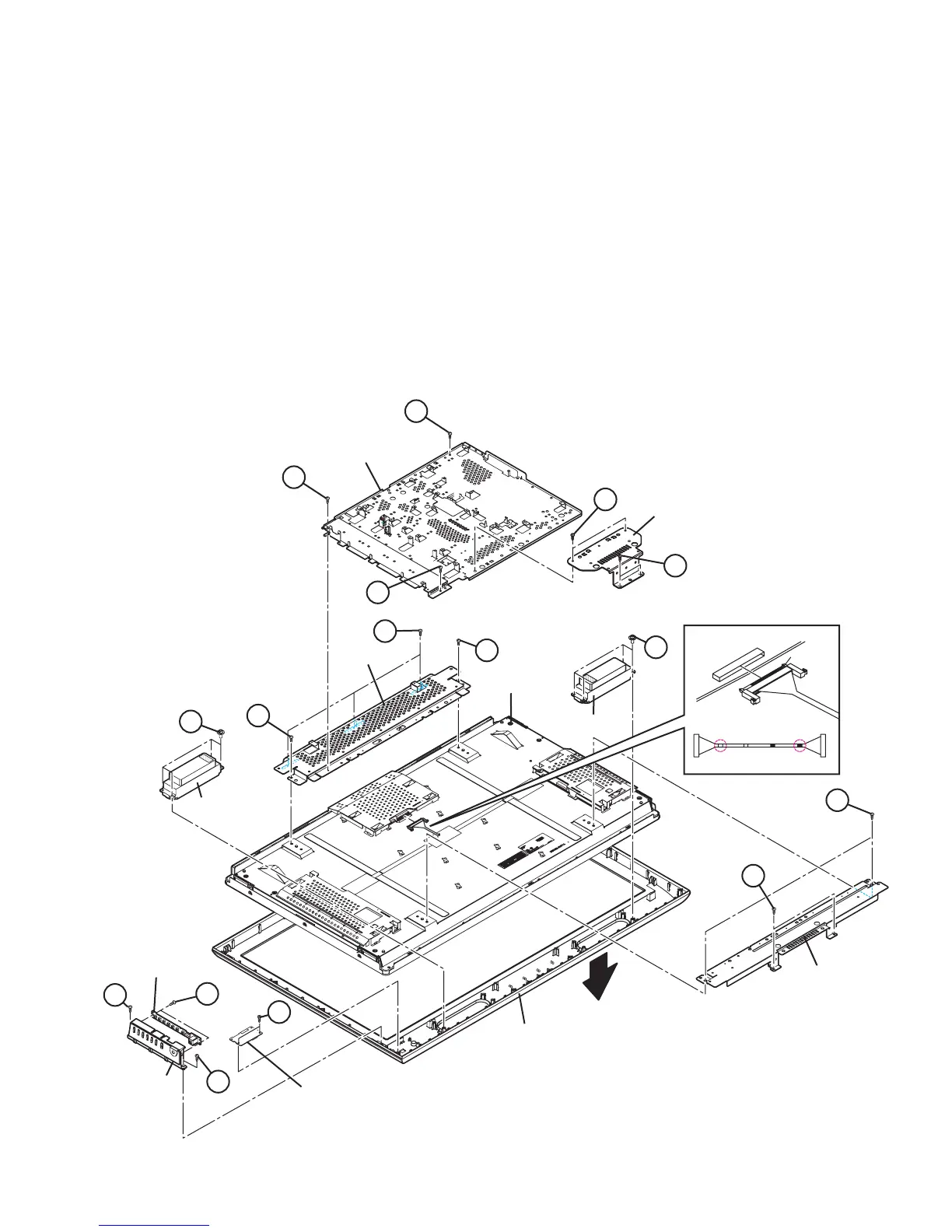
3.3.9 REMOVING THE SW PWB (Fig.4)
• Remove the STAND.
• Remove the REAR COVER.
(1) Remove the 2 screws [A].
(2) Remove the CONTROL ASS’Y with SW PWB.
(3) Remove the 2 screws [B].
(4) Remove the SW PWB from the CONTROL ASS’Y.
3.3.10 REMOVING THE LED PWB (Fig.4)
• Remove the STAND.
• Remove the REAR COVER.
(1) Remove the 2 screws [C].
(2) Remove the LED PWB.
3.3.11 REMOVING THE SPEAKER (Fig.4)
• Remove the STAND.
• Remove the REAR COVER.
(1) Remove the 4 screws [D].
(2) Remove the SPEAKER (L /R).
3.3.12 REMOVING THE LCD PANEL UNIT (Fig.4)
• Remove the STAND.
• Remove the REAR COVER.
• Remove the BACK BRACKET.
• Remove the POWER CORD HOLDER.
(1) Remove the 2 screws [E].
(2) Remove the STAND BRACKET.
(3) Remove the 3 screws [F].
(4) Remove the MAIN BASE.
(5) Remove the 4 screws [G] and 4 screw [H].
(6) Remove the LCD PANEL UNIT with TOP/BOTTOM
FRAME.
(7) Remove the 2 screws [J].
(8) Remove the TOP FARAME from the LCD PANEL UNIT.
(9) Remove the 2 screws [K].
(10) Remove the BOTTOM FARAME from the LCD PANEL
UNIT.
Fig.4
BOTTOM FRAME
TOP FRAME
MAIN BASE
STAND
BRACKET
FRONT
A
A
B
C
J
G
J
F
F
E
E
F
K
D
D
SPEAKER
SPEAKER
FRONT PANEL
LCD PANEL UNIT
CONTROL
ASS'Y
SW PWB
LED PWB
DIGITAL PWB SIDE
Check that connector is inserted completly.
(Don't insert aslant)
The terminal of a connector is turned up and connects.
Surely insert and lock.
white
Black
white
LCD PANEL SIDE
Black
"LVDS CABLE"
terminal side
H
 Loading...