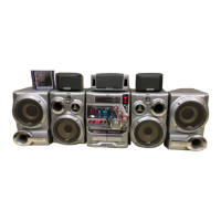
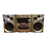
MX-DVB10
1-14
Prior to performing the following procedures, remove
the display & system control board.
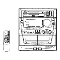
Removing the operation switch board
(See Fig.35, 36)
DVD eject board
FW915
(Soldered)
R
R
Fig.33
Fig.34
Fig.35
Preset / tuning switch board
S
S
Volume knob
Nut
SUBWOOFER
level knob
SOUND MODE knob
PRESET knob
FW901
(Soldered)
Operation switch board
Mic level knob
Fig.36
T
T
T
T
T
T
T
Joint g
Joint g
Joint g
Joints g
Joints g
Operation
switch board
T
Removing the DVD eject board
(See Fig.33)
Remove the three screws marked R attaching the
DVD eject board.
If necessary, unsolder FW915 on the DVD eject
board.
1.
2.
Pull out the PRESET knob on the front panel.
Remove the five screws marked S attaching the
preset / tuning switch board.
If necessary, unsolder FW901 on the preset / tuning
switch board.
1.
2.
3.
Removing the preset / tuning switch
board
(See Fig.34, 35)
Prior to performing the following procedures,
remove the display & system control board and
the preset / tuning switch board.
Pull out the volume knob on the front panel and
remove the nut. Pull out the SOUND MODE knob
and the SUBWOOFER level knob toward the front.
Pull out the mic level knob toward the front.
Remove the twelve screws marked T attaching the
operation switch board.
Release each tab of the seven joints marked g
retaining the operation switch board.
1.
2.
3.