(No.MB263)1-13
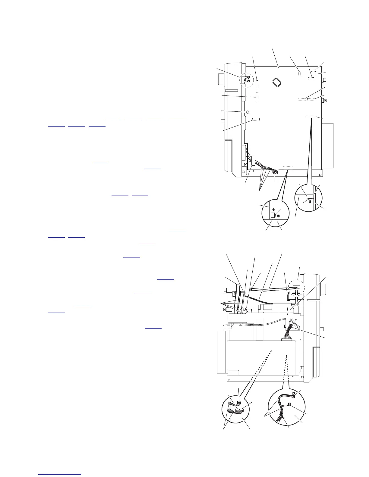
3.1.7 Removing the main board
(See Figs.14 and 15)
• Prior to performing the following procedures, remove the metal
cover, tuner, video board and rear panel.
(1) From the right side of the main body, remove the screw N
attaching the earth wires on the reverse side of the main
board. (See Fig.14.)
Reference:
After attaching the earth wires, fix them with a spacer as
before. (See Fig.14.)
(2) Remove the plastic rivet attaching the main board. (See
Fig.14.)
(3) From the inside of the main body, disconnect the card wires
from the connectors (CN11
, CN303, CN522, CN523,
CN524, CN860, CN880) on the forward side of the main
board. (See Figs.14 and 15.)
Reference:
When reassembly, pass the card wire through the sec-
tion f of the main board before connecting the card wire
to the connector CN11
. (See Figs.14 and 15.)
(4) Disconnect the wire from the connector CN454
on the for-
ward side of the main board. (See Figs.14 and 15.) [UW/
UE version only]
(5) Remove the wire clamp fixing the wires and disconnect the
wires from the connector (CN301
, CN302) on the forward
side of the main board. (See Fig.15.)
Reference:
After connecting the wires to the connectors, fix the wires
with the wire clamp as before. (See Fig.15.)
(6) Disconnect the parallel wire from the connectors (CN217
,
CN218, CN219) on the main board. (See Fig.15.)
(7) Release the lock g of the connector CN216 on the main
board in the direction of the arrow 1 and disconnect the
main board from the connector CN206
on the speaker ter-
minal board toward this side. (See Fig.14.)
Note:
When releasing the lock g of the connector CN216
, take
care not to break the lock. (See Fig.14.)
(8) Release the lock h of the connector CN201 on the primary
board in the direction of the arrow 2 and disconnect the
connector CN211
on the main board from the connector
CN201
in the direction of the arrow 3. (See Fig.14.)
Note:
When releasing the lock h of the connector CN201
, take care
not to break the lock. (See Fig.14.)
Fig.14
Fig.15
Main board
CN11 CN522
f
CN880
CN860
Plastic
rivet
CN303
Spacer
Main board
CN201 Primary board
Main
board
Speaker terminal
board
CN206 CN216
h
g
Earth wires
3
2
1
CN523
CN216
CN531
CN454
N
CN211
CN524
f
CN531
CN11
CN880
CN860
CN303
CN218
Main boardParallel wires
CN219
Card wire
Card
wires
CN524
CN454
CN522
Wire
CN217
CN301
CN302
Wires
Wire clamp
Main board
CN523