(No.MB263)1-19
3.1.15 Removing the switch board
(See Figs.23 to 25)
• Prior to performing the following procedures, remove the metal
cover and front panel assembly.
(1) From the front side of the front panel assembly, pull the mi-
crophone knob out of the front panel assembly. (See
Fig.23.) [US/UX/UN version only]
(2) From the inside of the front panel assembly, remove the
three screws X and screw X’ attaching the stay bracket.
(See Fig.24.)
Reference:
When attaching the screw X’, attach the earth wire with
it.
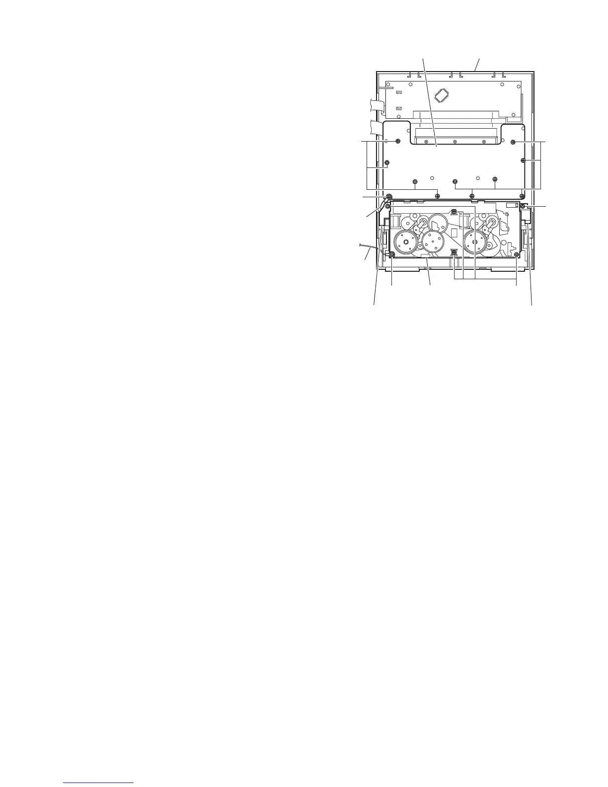
(3) Remove the ten screws Y and screw Y’ attaching the
switch board. (See Fig.25.)
Reference:
When attaching the screw Y’, attach the wire holder with
it.
(4) Take out the switch board from the front panel assembly.
3.1.16 Removing the cassette mechanism assembly
(See Fig.25)
• Prior to performing the following procedures, remove the metal
cover and front panel assembly.
(1) From the inside of the front panel assembly, remove the
five screws Z, screw Z’ attaching the cassette mechanism
assembly.
(2) Take out the cassette mechanism assembly from the front
panel assembly.
Reference:
• When attaching the screw Y’, attach the earth wire with it.
• When attaching the screws Z, attach the swing cam (L)/(R)
with them.
Fig.25
Z
Z
Front panel assembly
Swing cam (R)
assembly
Earth
wire
Swing cam (L)
assembly
Cassette mechanism
assembly
Y
Switch board
Y'
Z'
Wire
holder