MX-K1
1-8
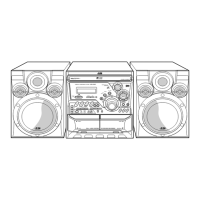
Fig.6
[Caution] Although the CD mechanism unit can be
removed without removing the CD tray
panel, it is still recommended to remove it
in order to prevent damage.
Prior to performing the following procedures,
remove the top cover.
a.
b.
c.
1.
2.
3.
4.
5.
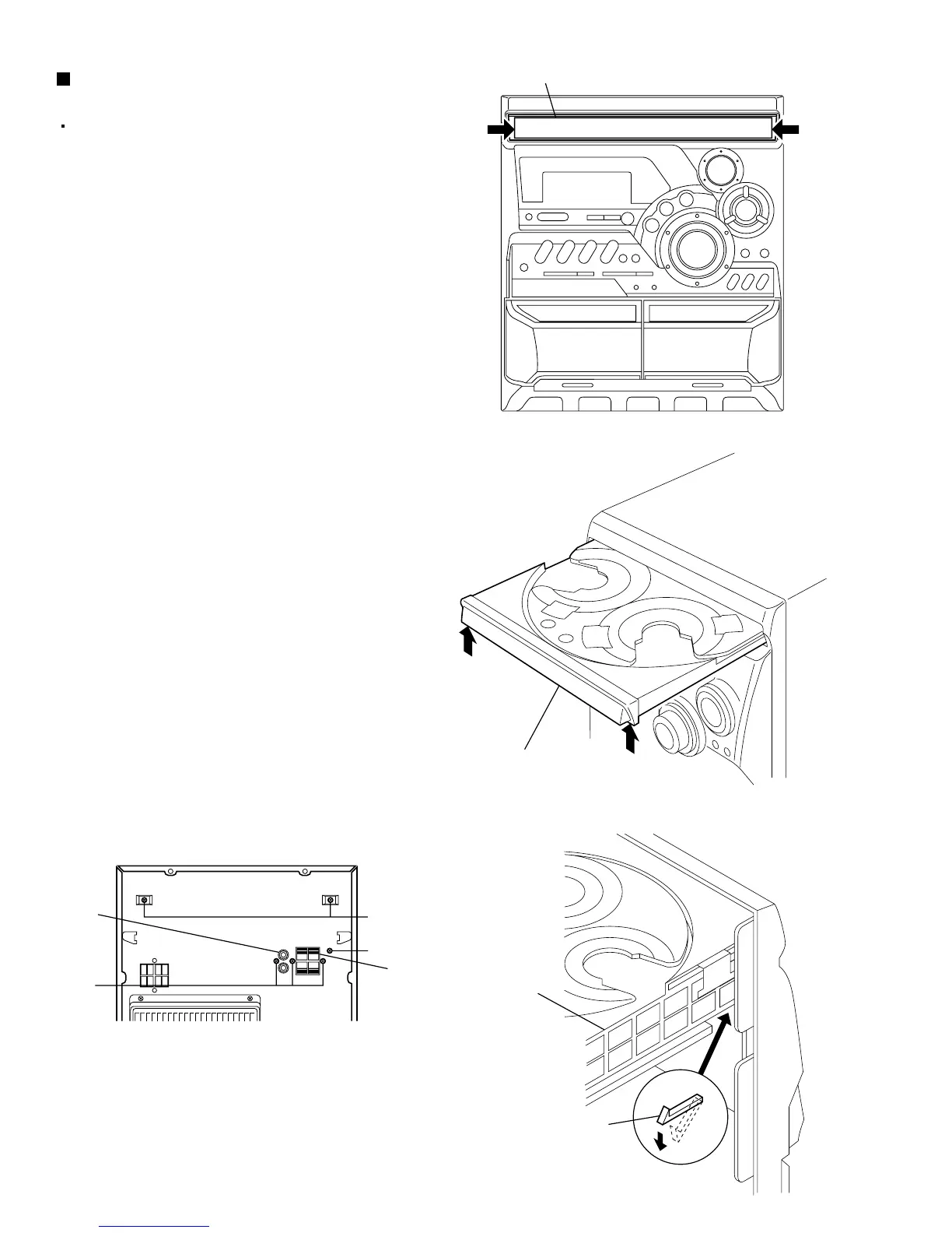
From the front panel side of this set, push in the
sections marked with arrows and pull out the CD
tray toward the front.
Remove the CD tray panel by pushing both of its
extremities upward in the direction of the arrows.
Push the CD tray deep into the set.
Disconnect the cassette head wires from the
connectors CN307 and CN308 on the main PCB,
which is located below the CD changer unit.
Disconnect the card wires from the connectors
CN301, CN302 and CN305 on the main PCB.
Disconnect the parallel wires from the connectors
CN902A, CN902B and CN902C on the power amp
and supply PCB.
From the rear of the set, remove the two screws
"D" retaining the CD changer unit, then remove the
three screws "E" and the screw "F" retaining the
ANTENNA terminal and the AUX IN terminal.
Push down and disengage the two claws "a"
holding the CD changer unit at the bottom of its
front panel and then remove the CD changer unit
(Fig. 9).
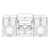
Removing the CD changer unit
(See Fig.6 to 9)
Fig.8
Fig.9
Fig.7
CD tray panel
CD tray panel
D
F
E
AUX IN
terminal
ANTENNA
terminal
CD changer
unit
Claw a