1-16 (No.MB284)
3.1.8 Removing the POWER switch board / CD switch board
(See Fig.25, 26)
• Prior to performing the following procedure, remove the front
panel assembly.
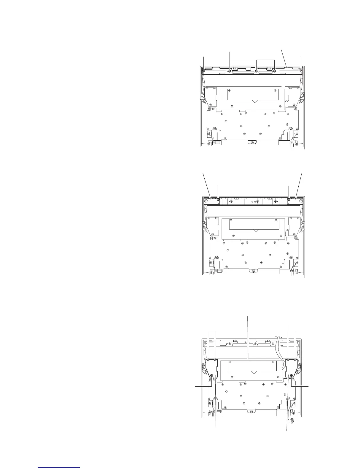
(1) Remove the two screws P and the three screws Q attach-
ing the bracket.
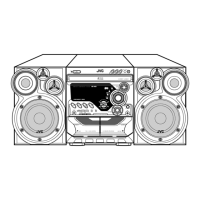
(2) Remove the screws R attaching the POWER switch board.
(3) Remove the screw T attaching the CD switch board.
Fig.25
Fig.26
3.1.9 Removing the REC select switch board / PROGRAM select switch board
(See Fig.27)
• Prior to performing the following procedure, remove the front
panel assembly.
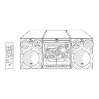
(1) Remove the three screws U attaching the REC select
switch board.
(2) Remove the three screws Y attaching the CD switch board.
Fig.27
P
Q
P
Front panel assembly
Bracket
RT
CD switch boardPower switch board
Front panel assembly
Y
Y
PROGRAM select
switch boaed
REC select
switch boaed
U
U
Front panel assembly