1-22 (No.MB350)
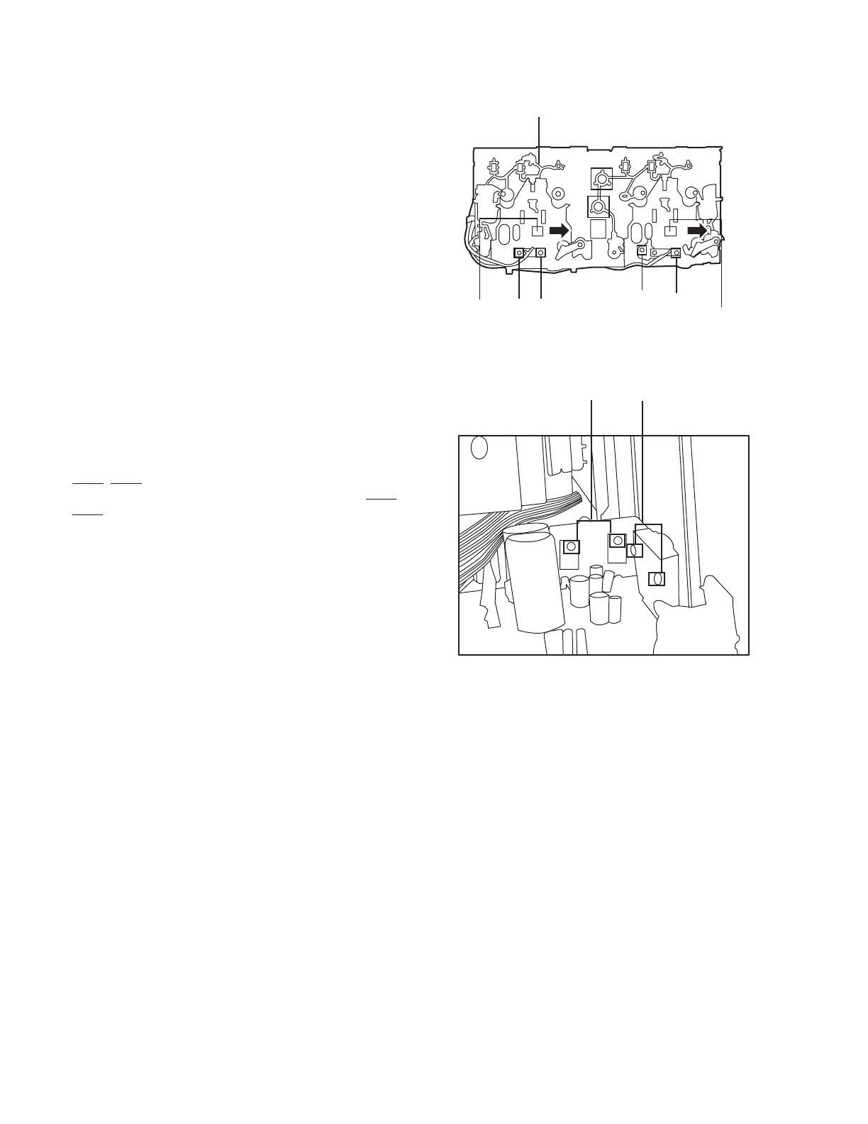
3.1.17 Removing the cassette deck heads
(See Fig. 39 and 42)
• Prior to performing the following procedures, remove the top
cover and both sides board.
• Also remove the CD changer unit.
• Also remove the front panel assembly.
(1) Remove six screws Z that retain the cassette deck mecha-
nism. (Fig.39)
(2) Remove the cassette deck mechanism and place it so that
the front side faces up.
(3) Remove the solder from the bottom side of the head termi-
nal and disconnect the wire.
(4) Remove screws U that retains the head.
(5) Remove screws V that retains the head.
(6) Hold the head and slide it in the direction of the arrow to re-
move it.
Fig.42
3.1.18 Removing the 3-pin regulator and bridge diode
(See Fig. 43)
• Prior to performing the following procedures, remove the top
cover and both sides board.
Remove two screws A that connect the heat sink.
(1) Remove two screws A that connect the heat sink.
(2) Remove two screws W that connect the heat sink.
(3) Remove the solder fixing the the 3-pin terminal regulator
Q604
, Q608.
(4) Remove the solder fixing the 4-pin bridge diode (D614
,
D615).
Fig.43
Cassette deck mechanism
(Front side)
V
U
PB Head
REC/PB Head
VU
A
W