LC72131 Pin Functions
Pin No.
Symbol (MFP pin Nos. are Type Functions Circuit configuration
in parentheses.)
V
SS
BO1
BO2
BO3
BO4
IO1
IO2
PD
AIN
AOUT
IFIN
21 (19)
7 (6)
8 (7)
9 (8)
10 (9)
11 (10)
13 (12)
18 (16)
19 (17)
20 (18)
12 (11)
Ground
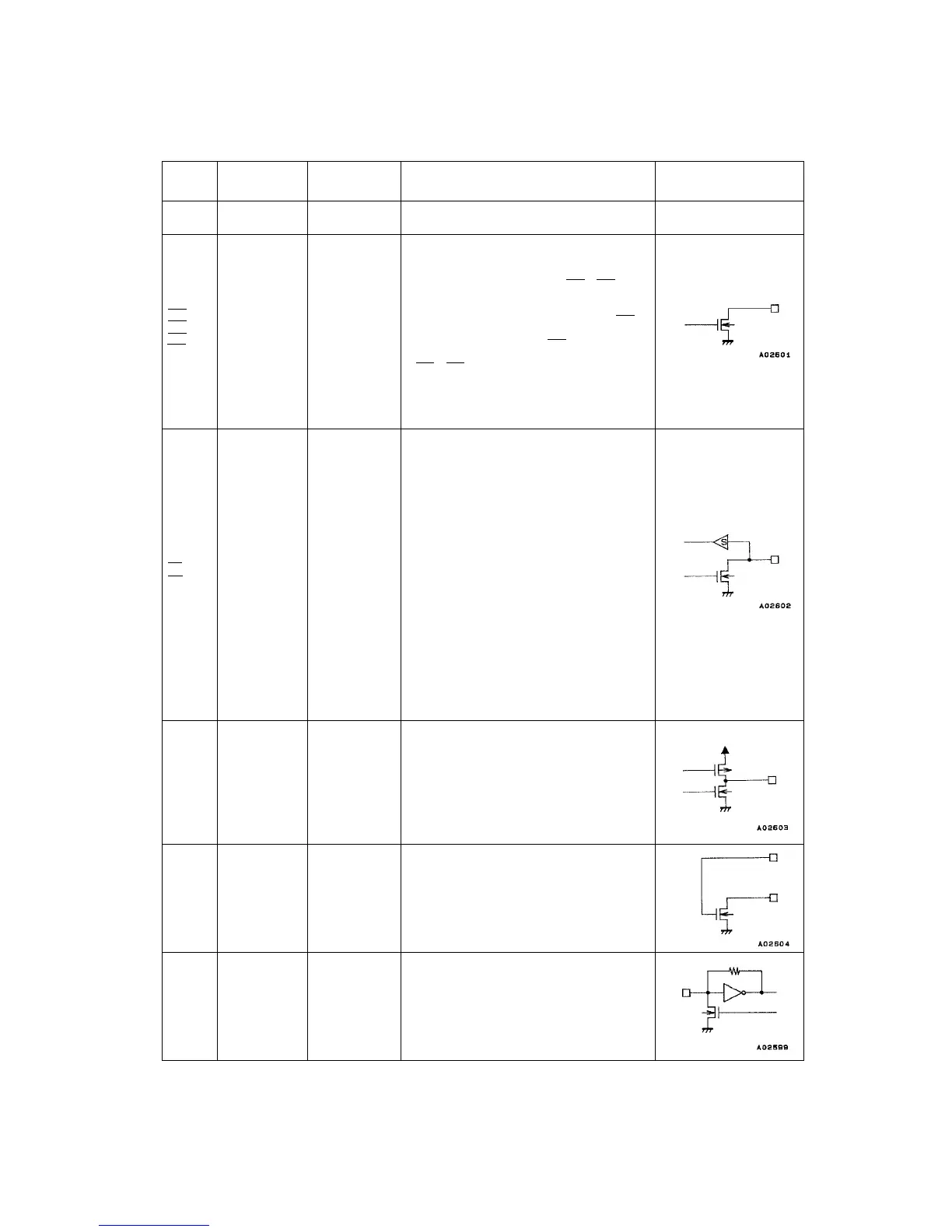
Output port
I/O port
Charge pump
output
LPF amplifier
transistor
IF counter
¥ The LC72131 ground Ñ
¥ Dedicated output pins
¥ The output states are determined by BO1 to BO4 bits in
the serial data.
Data: 0 = open, 1 = low
¥ A time base signal (8 Hz) can be output from the BO1
pin. (When the serial data TBC bit is set to 1.)
¥ Care is required when using the BO1 pin, since it has a
higher on impedance that the other output ports (pins
BO2 to BO4).
¥ All output ports are set to the open state following a
power on reset.
¥ I/O dual-use pins
¥ The direction (input or output) is determined by bits IOC1
and IOC2 in the serial data.
Data: 0 = input port, 1 = output port
¥ When specified for use as input ports:
The state of the input pin is transmitted to the controller
over the DO pin.
Input state: low = 0 data value
high = 1 data value
¥ When specified for use as output ports:
The output states are determined by the IO1 and IO2
bits in the serial data.
Data: 0 = open, 1 = low
¥ These pins function as input pins following a power on
reset.
¥ PLL charge pump output
When the frequency generated by dividing the local
oscillator frequency by N is higher than the reference
frequency, a high level is output from the PD pin.
Similarly, when that frequency is lower, a low level is
output. The PD pin goes to the high impedance state
when the frequencies match.
¥ The n-channel MOS transistor used for the PLL active
low-pass filter.
¥ Accepts an input in the frequency range 0.4 to 12 MHz.
¥ The input signal is directly transmitted to the IF counter.
¥ The result is output starting the MSB of the IF counter
using the DO pin.
¥ Four measurement periods are supported: 4, 8, 32, and
64 ms.
1 - 14
PC-X250
 Loading...