EasyManuals Logo

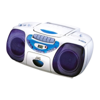
JVC RC-BX30 Schematic Diagrams

JVC RC-BX30
12 pages
To Next Page IconTo Next Page
To Previous Page IconTo Previous Page
Page #4 background imageLoading...
Page #4 background image
RC-BX30
2-2
RC-BX30
HAB C DE FG
1
2
3
4
5
Parts are safety assurance parts.
When replacing those parts, make
sure to use the specified one.
RADIO SIGNAL
TAPE PB SIGNAL
CD SIGNAL
TAPE REC SIGNAL
MAIN SIGNAL
From
Cassette board
CN203
From
Tuner board
CN101
Main board
From
CD module
To
Cassette board
CN204
0V
0.59V
5.68V
11.02V
10.6V
0V
0V
0.59V
5.7V
11.1V
10.7V
6.03V
2.27V
1.5V
0.93V
2.3V
1.5V
0.93V
9.13V
4.04V
3.38V
10.5V3.38V
3.9V
11.1V9.12V
10.6V
11.1V6.16V
6.76V
Standard schematic diagrams
Main section

Other manuals for JVC RC-BX30

Questions and Answers:

Question and Answer IconNeed help?

Do you have a question about the JVC RC-BX30 and is the answer not in the manual?

JVC RC-BX30 Specifications

General IconGeneral
BrandJVC
ModelRC-BX30
CategoryCD Player
LanguageEnglish

Related product manuals