1 Low frequency oscillator Reference measurement ----- 26.1mV(0.63/8)
This oscillator should have a capacity to output output
0dB to 600 at an oscillation frequency of Input positions ----- AM : Standard loop antenna
50Hz-20KHz FM : TP1 (hot) and TP2 (GND)
2 Electronic voltmeter
3 Distortion meter Precautions for measurement
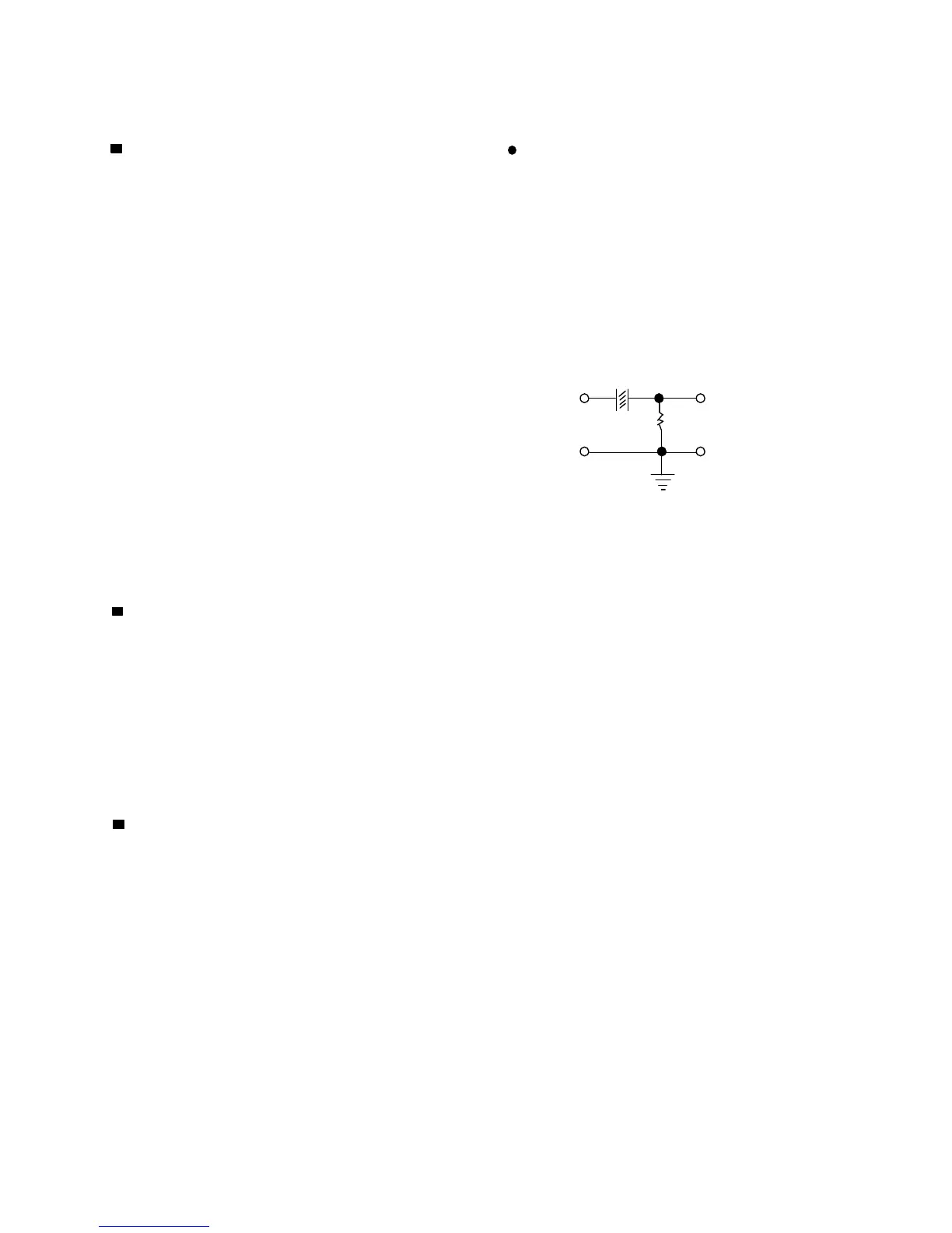
4 Frequency counter 1 Direct connect to the IF sweeper output
5 Wow & flutter meter side and 1UF and 22 Kohm connect to the
6 Test tape sweeper input side. Same as FIG1.
TCC-112: Tape speed and running unevenness (3KHz) 1 U
TCC-140: Reference level (1KHz) IC101 TP16
TCC-182A: Head angle (8KHz), playback frequency PIN18 22 K
characteristics (1KHz) and dubbing
frequency TP8
characteristics (125Hz and 8KHz)
7 Blank tape 2 The IF sweeper output level should be made as
TYPE I : TDK-D60 low as possible within the adjustable range.
3 Since the IF sweeper is a fixed device, there is
8 Torque gauge : For play and back tension no to adjust this sweeper.
FWD(CT-120m), and FF/REW(CT-F) 4 Since a ceramic oscillator is used, there is no
need to perform any MIX adjustment.
Measurement conditions 5 Since a fixed coil is used, there is no need to
adjustment the FM tracking.
Power supply voltage -------------- AC120V (60Hz) 6
Reference output -------------- Speaker : 0.63V/8 In case of simultaneously measuring the voltage
Headphone : 0.245V/32 in both of the input and output systmes with and
electronic voltmeter for two channels, therefore,
the earth should be connected particularly
Input for confirming recording and ------- CD : -10dB carefully.
playback characteristics 7 For connecting a dummy resistor when measuring
Measurement output terminal ------- Speaker CN301 the output, use the wire with a greater code size.
* Load resistance -------------------------------------- 8 8 Whenever any mixed tape is used, use the band
pass filter (DV-12V).
Radio Input signal
AM frequency -------------------------------- 400Hz
AM modulation ---------------------------------- 30%
FM frequency --------------------------------- 1 KHz
FM frequency deviation ------------------ 22.5KHz
1-7