(No.MB269)1-11
3.16 Removing the system control board and power switch board
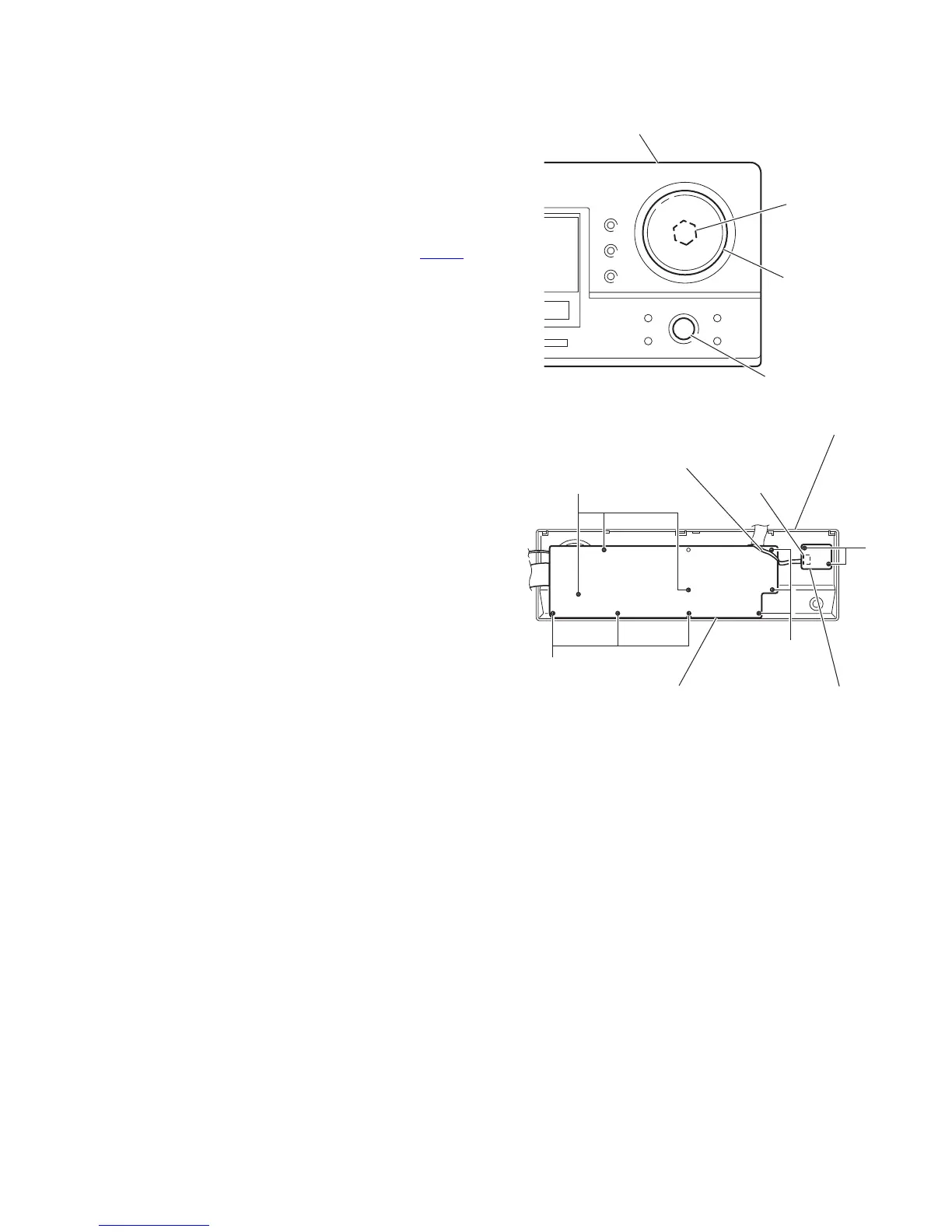
(See Figs.18 and 19)
• Prior to performing the following procedures, remove the top
cover and front panel assembly.
(1) Pull out the volume and jog knobs from the front side of the
front panel assembly, remove the nut attaching the system
control board. (See Fig.18)
(2) From the back side of the front panel assembly, remove the
nine screws W attaching the system control board. (See
Fig.19)
(3) Disconnect the parallel wire from the connector CN714
on
the power switch board. (See Fig.19)
(4) Take out the system control board from the front panel as-
sembly.
(5) Remove the two screws X attaching the power switch
board. (See Fig.19)
(6) Take out the power switch board from the front panel as-
sembly.
Fig.18
Fig.19
Nut
Volume knob
Front panel assembly
Jog knob
W
W
W
X
Power switch board
System control board
Parallel wire
Front panel assembly
CN714
 Loading...