Do you have a question about the JVC rx-555bk and is the answer not in the manual?
Controls for power and the graphic equalizer.
Explains various indicators on the front panel.
How to tune stations and use preset functions.
Details on PRESET SCAN and AUTO MEMORY functions.
How to adjust volume and speaker balance.
Temporarily mutes the audio output.
Overview of the COMPU LINK system and remote functionality.
Explains various remote control buttons and their uses.
Operating VCR and TV channels via the remote.
Operating tape decks and DAT decks via the remote.
Using auto search and CD changer functions remotely.
Controlling surround processor functions remotely.
Steps for removing the top cover and front panel.
Steps for removing the SEA, Front Switch, and LCD PCBs.
Steps for removing the power transistors.
Alignment for FM front-end, IF, MPX, and stereo separation.
Alignment procedures for LW and MW sections.
External diagram and pin functions for the tuner controller IC.
External diagram and pin functions for the system controller IC.
Block diagram for the LA1266A tuner IC.
Block diagram for the LA3401 PLL IC.
Internal block diagram of the PLL synthesizer IC.
Block diagram and pin functions for the volume control IC.
Block diagram for the TC9164N LCD driver IC.
Block diagram for the TC9162N LCD driver IC.
Block diagram for the LA3607S ICs.
Block diagram for the VC5022-2 ICs.
Block diagram for the TA7317P IC.
List of components used in the remote control.
Diagram showing the button layout of the remote control.
Diagram showing the terminal layout for the LCD.
Wiring details for LCD source and tuner sections.
Block diagram of the tuner section.
Block diagram of control and amplifier sections.
Overview of major component locations within the unit.
Visual representation of parts and their corresponding list.
Detailed parts lists for various PCB assemblies.
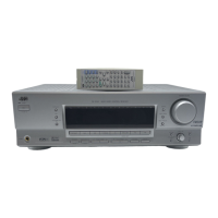
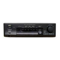
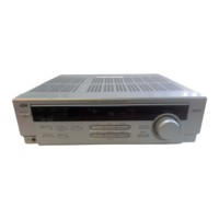
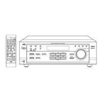
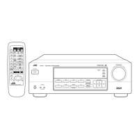
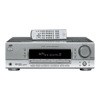
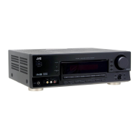
Identification of main parts from the front view.
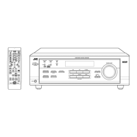
Identification of main parts from the top view.
Identification of main parts from the rear view.
Lists diodes and transistors with part numbers.
Lists capacitors and resistors with part numbers.
Lists other components like screws, spacers, etc.
Lists diodes and transistors for the power amplifier PCB.
Lists ICs and capacitors for the power amplifier PCB.
Lists capacitors for the tuner PCB.
Lists resistors for the tuner PCB.
Lists transistors and ICs for the tuner PCB.
Lists diodes for the tuner PCB.
Lists capacitors for the tuner PCB.
Lists resistors for the tuner PCB.
Lists resistors for the tuner PCB.
Lists miscellaneous parts for the tuner PCB.
Lists diodes and transistors for the control & display PCB.
Lists capacitors for the control & display PCB.
Lists resistors for the control & display PCB.
Lists resistors for the control & display PCB.
Lists miscellaneous parts for the control & display PCB.
Lists capacitors and resistors for the surround & switch PCB.
Lists diodes for the surround & switch PCB.
Lists transistors for the pre-driver module PCB.
Lists transistors and diodes for the pre-driver module PCB.
Lists capacitors and resistors for the pre-driver module PCB.
Lists miscellaneous parts for the pre-driver module PCB.
| Channels | 5.1 |
|---|---|
| Frequency Response | 10 Hz to 50 kHz |
| Speaker load impedance | 8 ohms |
| Tuning range | FM, AM |
| Total Harmonic Distortion | 0.08% |
| Signal-to-Noise Ratio | 95dB (line) |
| Video Connections | composite |