2-1
RX-6000VBK/RX-6008VBK/RX-6100VBK
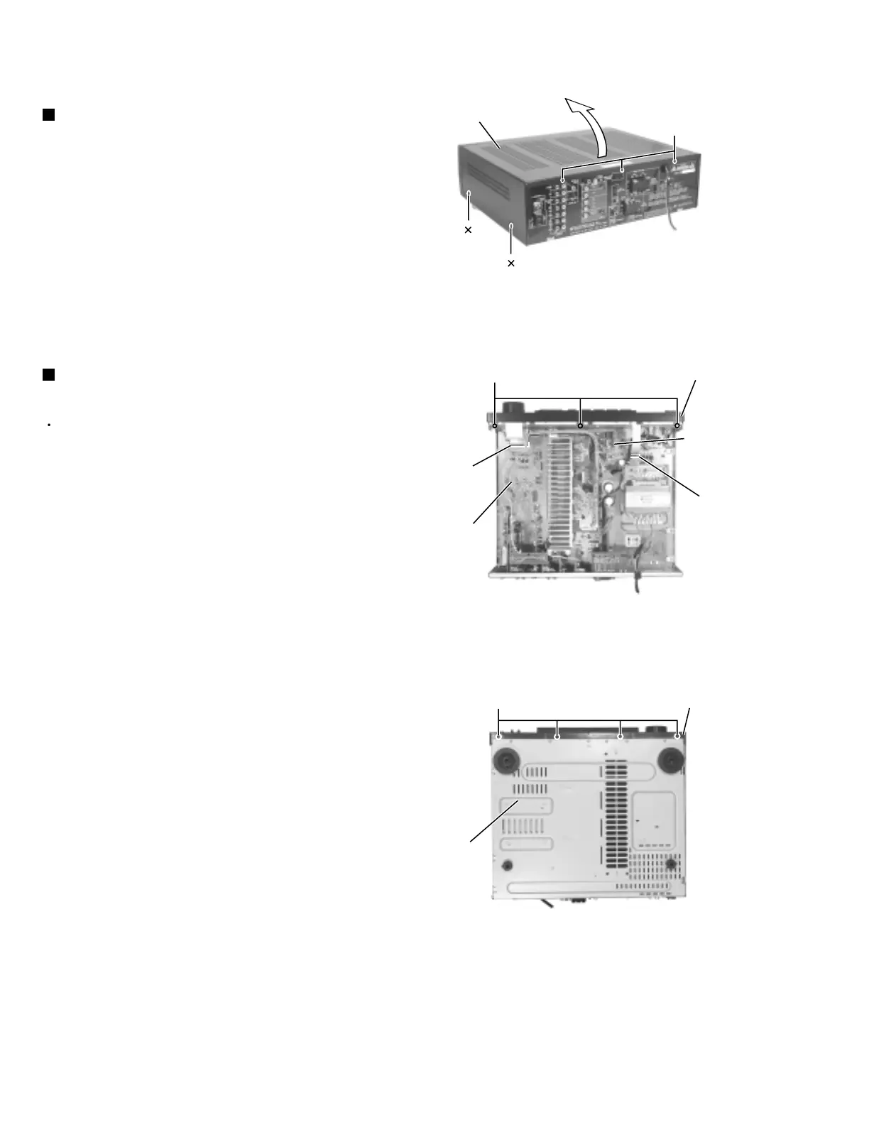
Remove the four screws A attaching the top cover
on both sides of the body.
Remove the three screws B on the back of the body.
Remove the top cover from behind in the direction of
the arrow while pulling both sides outward.
1.
2.
3.
Disassembly method
Removing the top cover (See Fig.1)
Prior to performing the following procedure, remove
the top cover.
Disconnect the harness from connector CN314 on
the volume control board and connector CN811 on
the main board.
Remove the three screws C attaching the front
panel assembly.
Remove the four screws D attaching the front panel
assembly on the bottom of the body.
1.
2.
3.
Removing the front panel assembly
(See Fig.2 and 3)
Top cover
Volume control
board
CN314
Main board
Front panel assembly
A 2
B
C
D
Front panel assembly
Bottom cover
Fig.1
Fig.2
Fig.3
CN811
A 2

 Loading...