RX-6000VBK/RX-6008VBK/RX-6100VBK
2-2
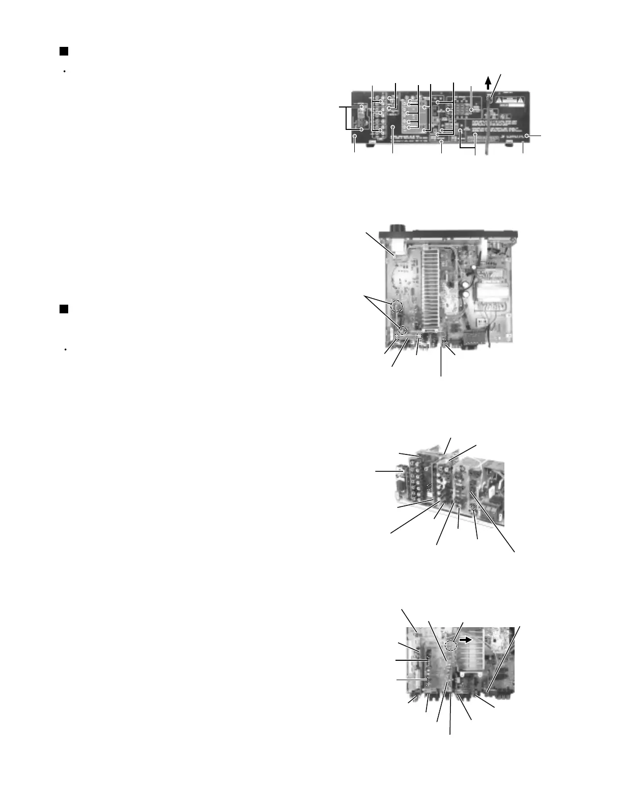
Prior to performing the following procedure, remove
the top cover.
Remove the power cord stopper while moving it in
the direction of the arrow.
Remove the twenty-two screws E attaching each
board to the rear panel.
Remove the three screws F attaching the rear panel
on the back of the body.
1.
2.
3.
Removing the rear panel (See Fig.4)
Prior to performing the following procedure, remove
the top cover.
For the harness extending from the AV compulink &
sub woofer board to the volume control board,
disconnect it from connector CN617 on the volume
control board and cut off the two tie bands.
Disconnect the AV compulink & sub woofer board
from connector CN616 on the volume control board.
Disconnect the relay board 1 from connector CN609
on the video terminal board and CN603 on the audio
board.
Disconnect the S-video board from connector CN618
on the volume control board.
Disconnect the video terminal board from connector
CN614 on the volume control board.
Release joint a of the lower part of the DSP board
and the bracket. Disconnect the DSP board from
connector CN651 and CN657 on the volume control
board.
Disconnect the audio board from connector CN611
and CN612 on the volume control board.
Disconnect the tuner board from connector CN121
on the volume control board.
1.
2.
3.
4.
5.
6.
7.
Removing each board connected to the
volume control board (See Fig.5 to 7)
E
Power cord stopper
Rear panel
F
Volume control board
CN617
Tie bands
Relay board 1
CN603
CN609
AV compulink & sub woofer board
Audio board
CN603
Video terminal board
CN609
S-video board
DSP board
CN614
AV compulink &
sub woofer board
Tuner board
Joint a
E
E
E
E
E
E
E
F
F
Fig.4
Fig.5
Fig.6
Fig.7
Volume control board
CN616
Tuner board
Relay board 1
Video terminal board
CN618
CN616
Volume control board
CN121
CN611
CN612
Audio board
DSP board
AV compulink &
sub woofer board
S-video board
CN651
CN657
E
Video terminal board
 Loading...