2-3
RX-6000VBK/RX-6008VBK/RX-6100VBK
Prior to performing the following procedure, remove
the top cover and the rear panel.
Disconnect the card wire from connector CN314 on
the volume control board.
Cut off the three tie bands fixing the harness.
Disconnect the harness from connector CN712 on
the preamplifier board.
Disconnect the relay board from connector CN615
on the volume control board and CN851 on the main
board.
Remove the five screws G attaching the volume
control board.
1.
2.
3.
4.
5.
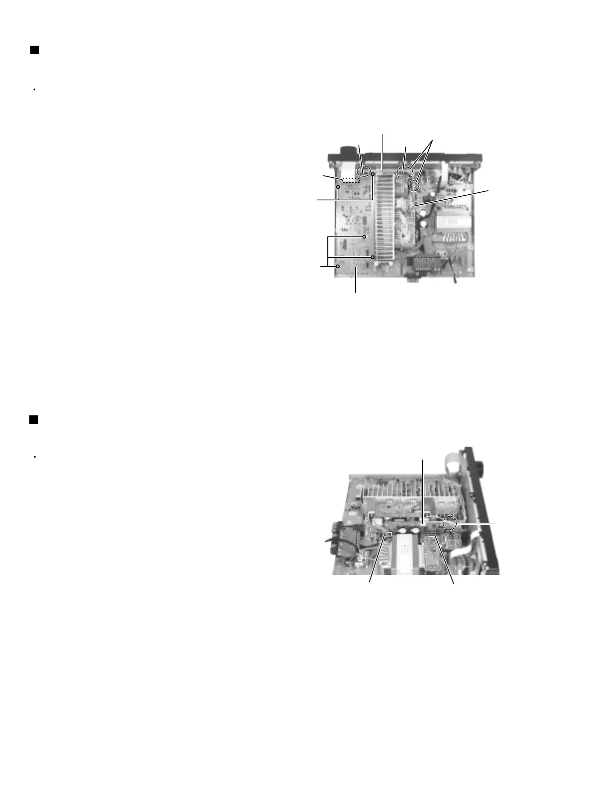
Removing the volume control board
(See Fig.8)
Prior to performing the following procedure, remove
the top cover.
Disconnect the harness from connector CN712 on
the preamplifier board and cut off the one tie band.
Disconnect the preamplifier board from connector
CN711 and CN713 on the main board.
1.
2.
Removing the preamplifier board
(See Fig.9)
It is not necessary to remove the
boards inserted to the back of the
volume control board.
ATTENTION:
Preamplifier
board
CN712
G
Fig.8
Fig.9
Tie band
CN615
CN851
Tie bands
G
Volume control board
Relay board
Preamplifier board
CN712
Main board
CN713
Main board
CN711
Tie band
CN314
 Loading...