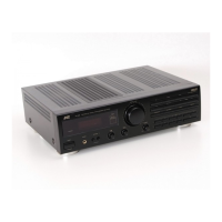
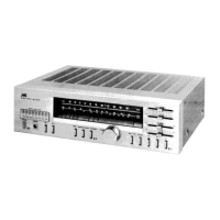
RX-7520VBK
1-4
Remove the four screws A attachin
the top cover on
both sides of the bod
Remove the three screws B on the back of the bod
Remove the top cover from behind in the direction of
the arrow while pullin
both sides outward
3
D
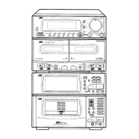
sassembl
metho
Removin
the top cover (See Fi
.1
Prior to performin
the followin
procedure, remove
the top cover
Remove the power cord stopper from the rear panel
by movin
it in the direction of the arrow
Remove the twenty-six screws E attachin
the each
boards to the rear panel on the back of the bod
Remove the four screws F attachin
the rear panel
on the back of the bod
Removin
the rear panel (See Fi
.4
Prior to performin
the followin
procedure, remove
the top cover
Disconnect the card wire from connector
N4
2 on
the audio board and CN201 on the power suppl
board in the front panel assembl
Cut off the tie band fixin
the harness
Remove the three screws C attachin
the front panel
assembl
Remove the four screws D attachin
the front panel
assembl
on the bottom of the bod
. Detach the front
panel assembl
toward the front
Removin
the front panel assembly
(See Fi
.2 and 3
Fi
.
Fi
.
Fig.3
Fig.4
A
2
A
2
B
C
ower suppl
o
r
N4
M
i
o
r
Ti
n
E
E
F
E
F
F
Cord stoppe
Front panel assembl
Rear panel
CN201
E
E
E
E
 Loading...