Do you have a question about the JVC CA-C55BK and is the answer not in the manual?
Perform isolation check on exposed metal parts to ensure product safety without a line isolation transformer.
Dangers of invisible laser radiation, serviceability, and general handling precautions.
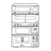
Install batteries, connect speakers, antennas, and auxiliary equipment for system setup.
Connect feeder antenna, 75-ohm cable, and outside antennas for optimal reception.
Connect turntables, VCRs, and other devices, ensuring proper cord placement.
Using volume, balance, bass extension, headphones, and sound effect modes.
Preparing discs, loading magazine, and starting CD playback.
Intro Scan, Random Play, Program Play for managing CD tracks.
Options for playing CDs in random order or a user-defined sequence.
Regular Play, One Touch Play, fast winding, and Music Scan for cassette tapes.
Reverse Mode, Continuous Play, Dolby NR, and general recording guidelines.
Standard, CD Direct, and other techniques for transferring audio onto tape.
Methods for recording CD content to tape and dubbing tapes between decks.
Procedures for high speed dubbing, setting timers, and tuning radio stations.
Cancelling presets, scanning stations, setting clock, and configuring timers.
Understanding timer priority and how to check remaining time for Wake Up/Sleep timers.
Setting the timer to wake the user with audio from CD, tape, or radio.
Setting the timer to automatically turn off the unit after a specified duration.
Using the remote for system functions and its numeric keypad.
Proper handling and storage of CDs, tapes, and general unit maintenance.
Details on LSIs, connections, disassembly, adjustments, operation flows, diagrams, and PCBs.
Pinout and function details for the system controller IC.
Pinout and function details for the system controller IC.
Block diagrams and descriptions for echo circuit and DC motor driver ICs.
Block diagrams and descriptions for delay and ALC circuit ICs.
Block diagrams, layouts, and descriptions for equalizer filter and NR amplifier ICs.
Visual layout and pin mapping for the FL display.
Procedures for removing the top cover, front panel assembly, heatsink, rear panel, and power IC.
Steps to remove front circuit board, cassette mechanism, holders, lids, and deck boards.
Steps for removing head assembly, capstan motor, and reel/cam motor.
Steps for removing pinch roller assembly, flywheel, and cam switch circuit board.
Required instruments and procedures for measuring torque and wow/flutter.
Steps for adjusting head azimuth and various torque parameters.
Adjusting playback level, frequency response, and recording bias for optimal performance.
Adjusting playback sensitivity and checking erase ratio and auto-stop functions.
Verifying the correct operation of the Music Scan feature.
Electrical schematics for the playback amplifier stages of Deck A and Deck B.
Details of the HD614081SE07 IC491 deck controller.
Schematics for ENB-179-4, ENB-238-2, ENB-179-8.
Schematics for ENB-238-1 and ENB-179-7.
Schematics for ENB-179-1 and ENB-238-3.
Schematics for ENB-179-4 and ENB-238-2.
Schematics for ENB-179-1 and ENB-238-3.
Schematics for ENB-179-8, ENB-238-4, and ENB-238-7.
Schematics for record amplifier and deck equalization circuits.
Schematic related to the reel speed control mechanism.
Layout and parts for the ENB-179 PC board.
Layout and parts for the ENN-238 PC board.
Details on LSIs, connections, disassembly, adjustments, operation flows, diagrams, and PCBs.
Pinout, key matrix, and detailed pin functions for the tuner controller IC.
Pinout, key matrix, and detailed pin functions for the CD system controller IC.
Descriptions for BTL driver, reset IC, and dual OP amp ICs.
Pinout and block diagram for the digital servo and signal processor IC.
Pinout, block diagram, and pin functions for the D/A converter IC.
Pinout and block diagram for the RF and servo amplifier IC.
Main functions, terminal layout, and block diagram for the PLL synthesizer IC.
Main functions, terminal layout, and block diagram for the FM MPX detector IC.
Main functions, top view, block diagram, and pin description for the FM/AM IF AMP IC.
Visual layout and pin mapping for the FL display.
Procedures for removing the top cover, CD-Tuner PCB, front door mechanism, front panel, indicator PCB, and changer mechanism.
Steps for removing the magazine, turntable base, and exchanging the pickup.
Procedures for disassembling magazine holder and lifter unit assembly.
Steps for removing and mounting the P1 rail base and spindle motor.
Adjusting AM/FM tuning voltages and FM center meter.
Setting the clock for timer functions using a frequency counter.
Assessing laser diode health and measuring drive current.
Step-by-step guide for replacing the laser pickup assembly.
Layout and parts list for the ENB-182 PC board.
Layout and parts list for the ENA-149 PC board.
Illustrated breakdown of major assemblies and their corresponding parts.
Lists of included accessories, packing materials, and their part numbers.
Parts list and layout for the ENH-238 PC board.
Lists of transistors, diodes, and capacitors with their part numbers and areas.
Lists of diodes and capacitors with their part numbers and areas.
Lists of capacitors and resistors with their part numbers and areas.
Lists of resistors and other miscellaneous parts with their part numbers and areas.
Lists of resistors and other miscellaneous parts with their part numbers and areas.
Parts lists for transistors, diodes, ICs, and capacitors with their details.
List of other components like network resistors and connectors.
Comprehensive parts lists for various electronic components.
Illustrated breakdown of major assemblies and their corresponding parts.
Parts lists for the ENA-149 CD & Tuner and ENB-182 System Controller PC boards.
Parts list and layout for the ENA-149 PC board.
Lists of transistors, diodes, and capacitors with their part numbers and areas.
Comprehensive parts lists for various electronic components.
| Brand | JVC |
|---|---|
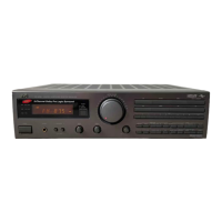
| Model | CA-C55BK |
| Category | Stereo Receiver |
| Language | English |