RX-8012VSL/RX-8010VBK
1-6
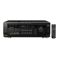
Remove the ten screws K and four screws L
attaching the heat sink.
Remove the two screws L' attaching the heat sink
from the rear side of main board.
1.
2.
Removing the heat sink
(See Fig.15 to 16)
Prior to performing the following procedure, remove
the top cover, the rear panel and audio board.
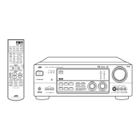
Cut off the tie band fixing the harness.
Disconnect the harness from connector CN811 on
the power supply board respectively.
Disconnect the harness from connector CN881 on
the main board.
Remove the four screws I and the four screws J
attaching the main board.
1.
2.
3.
4.
Removing the main board (See Fig.14)
Prior to performing the following procedures, remove
the top cover and the rear panel.
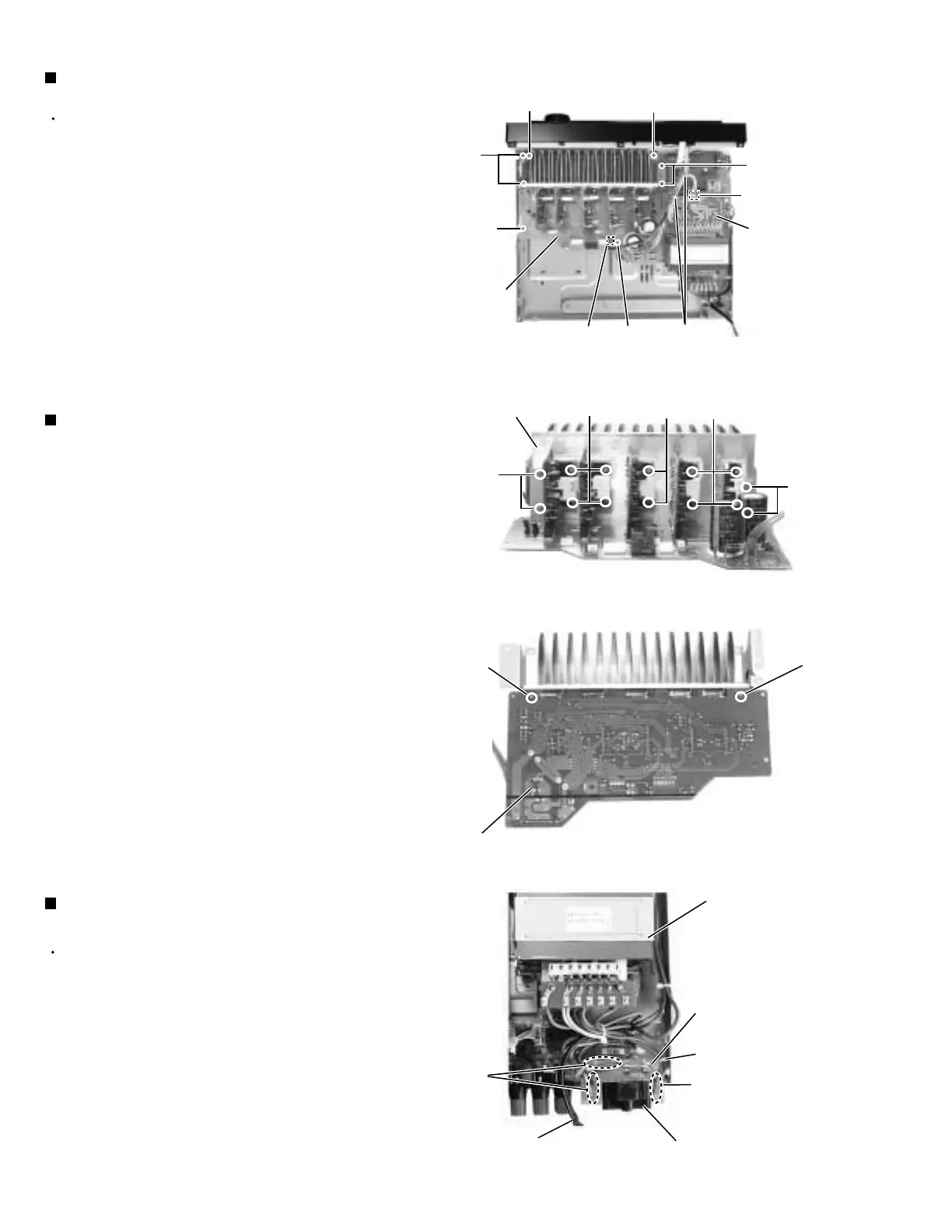
Cut off the tie band fixing the harness.
Unsolder the six harnesses connected to the power
transformer.
1.
2.
Removing the voltage select board
(See Fig.17)
Fig.14
Main board
rear side
Heat sink
L
L
K
K
K
L'
Fig.15
Fig.16
Main
board
I
CN881
I
J
J
I
I
Tie band
CN811
Power transformer
Solder points
Solder
points
Tie band
Power cord
Voltage select board
Voltage selector
Fig.17
L'
Power
supply
board
 Loading...