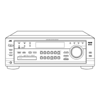
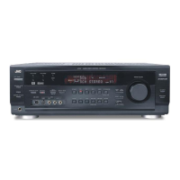
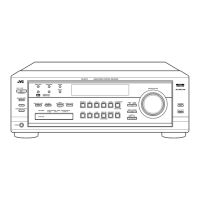
RX-8012VSL/RX-8010VBK
1-5
Prior to performing the following procedure, remove
the top cover and the tuner board, audio input board,
video audio board, video board, S-video board, DVD
board and the rear panel.
Removing the audio board
(See Fig.12 to 13)
Disconnect the harness from connector CN813 and
CN814 on the main board.
Disconnect the card wire from connector CN931 and
CN932 on the audio board.
Cut off the tie band fixing the harness.
Disconnect the relay board from the audio board and
the power supply board. (CN71,CN81)
Disconnect the card wire from connector CN831 on
the main board.
Remove the three screws G attaching the audio
board.
Remove the screw H attaching the audio board .
1.
2.
3.
4.
5.
6.
7.
Fig.10
Fig.11
Power
supply
board
Power / Fuse
board
Relay board
Audio board
CN71
CN81
H
CN814
CN813
CN931/ 932
Power
transformer
G
G
Tie band
CN831
Main
board
Fig.12
DSP board
CN601
Video
board
S Video
board
Video audio
board
Fig.13
Voltage
select
board
 Loading...