6
English
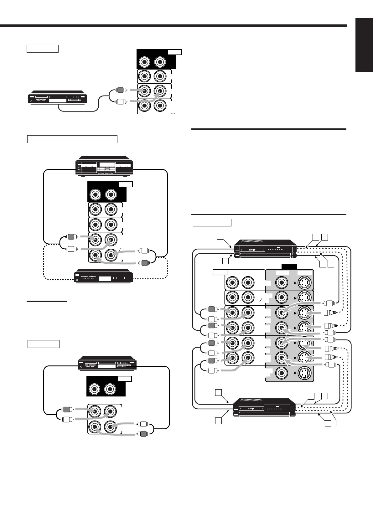
Video component connections
Use the cables with RCA pin plugs (not supplied).
Connect the white plug to the audio left jack, the red plug to the
audio right jack, and the yellow plug to the video jack.
• If your video components have S-video (Y/C-separation) and/or
component video (Y, P
B/CB, PR/CR) terminals, connect them using
an S-video cable (not supplied) and/or component video cable (not
supplied). By using these terminals, you can get a better picture
quality in the order — Component video > S-video > Composite
video.
IMPORTANT:
This receiver is equipped with the following video terminals —
composite video, S-video and component video terminals. You can
use any of the three to connect a video component.
However, remember that the video signals from one type of these
input terminals are output only through the video output
terminals of the same type.
Therefore, if a recording video component and a playing video
component are connected to the receiver through the different video
terminals, you cannot record the picture from the playing component
on the recording component. In addition, if the TV and a playing video
component are connected to the receiver through the different video
terminals, you cannot view the playback picture from the playing
component on the TV.
A
B
E
F
A
B
D
E
VIDEO
FRONT
RIGHT LEFT
DVD
TV SOUND
DBS
OUT
(REC)
IN
(PLAY)
VCR1
OUT
(REC)
IN
(PLAY)
VCR2
MONITOR
OUT
S-VIDEOVIDEO
AUDIO
DC
F
C
S-VHS (or VHS) VCR
Å To left/right channel audio output
ı To left/right channel audio input
Ç To S-video output
Î To composite video output
‰ To composite video input
Ï To S-video input
VCR(s)
S-VHS (or VHS) VCR
If your audio components have a COMPU LINK or TEXT
COMPU LINK jack
• See also page 41 for detailed information about the connection and
the COMPU LINK remote control system.
• See also page 42 for detailed information about the connection and
the TEXT COMPU LINK remote control system.
OUT
(REC)
IN
(PLAY)
RIGHT LEFT
REAR
AUDIO
CDR
CD recorder
To audio input
To audio output
CD recorder
Cassette deck or MD recorder
To audio output
To audio input
To audio input
IN
(PLAY)
OUT
(REC)
RIGHT LEFT
REAR
AUDIO
PHONO
TAPE
MD
CD
Note:
You can connect either a cassette deck or an MD recorder to the
TAPE/MD jacks. When connecting an MD recorder to the TAPE/MD
jacks, change the source name, which will be shown on the display
when selected as the source, to “MD.” See page 16 for details.
To audio output
Cassette deck
MD recorder
CD player
To audio output
IN
OUT
(REC)
RIGHT LEFT
REAR
AUDIO
PHONO
TAPE
MD
CD
CD player
EN01_10.RX-8012V[UW]_f 01.2.14, 11:51 AM6
 Loading...