EasyManuals Logo

JVC RX-D201 User Manual

JVC RX-D201
105 pages
To Next Page IconTo Next Page
To Previous Page IconTo Previous Page
Page #12 background imageLoading...
Page #12 background image
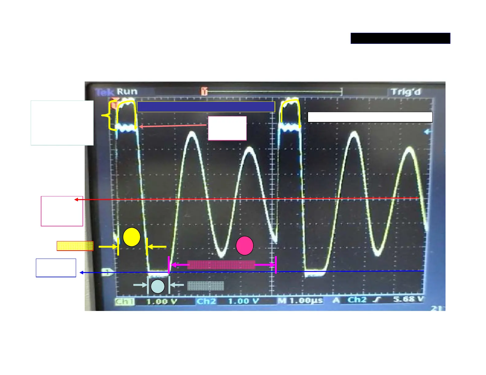
Waveform (1) at ‘AMP_+/-B’ switch regulator
The waveforms at Source and Gate of Q1101. Three periods in one cycle of
oscillation: 1.Q1101 turned on; 2. D1107 turned on by CEMF; 3. Damped LC
oscillation; Q1101 is switched off during period 2 and 3.
0 V.
AMP+B
(+30V.)
Yellow at G of Q1101 –channel 2
Blue at S of Q1101- channel 1
There is 10v At
Gate higher than
Source for
switches Q1101
on.
+B
(+60V.)
Damped oscillation
D1107 on
Q1101 on
1
2
3
POWER SUPPLY 3/5

Questions and Answers:

Question and Answer IconNeed help?

Do you have a question about the JVC RX-D201 and is the answer not in the manual?

JVC RX-D201 Specifications

General IconGeneral
BrandJVC
ModelRX-D201
CategoryReceiver
LanguageEnglish

Related product manuals