RX-DP10VBK/RX-DP10VSL
RX-DP10RSL
1-7
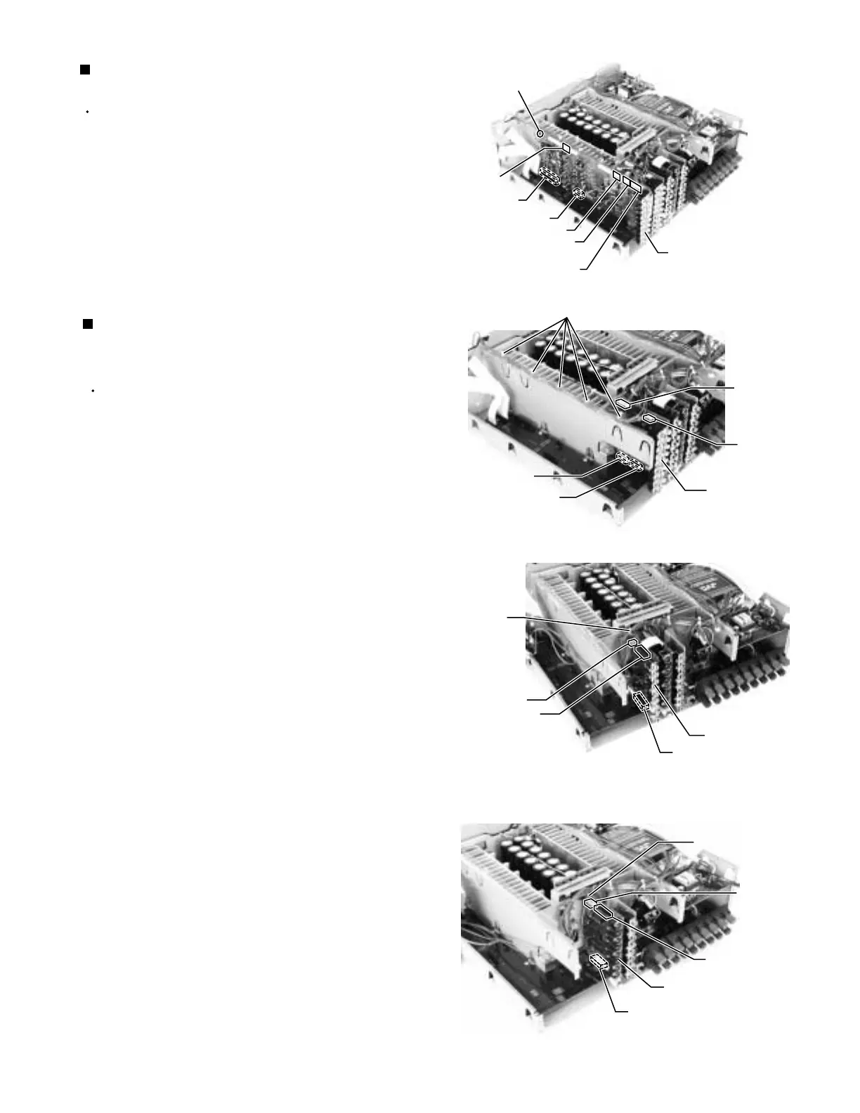
Prior to performing the following procedure, remove
the top cover, the rear panel and the DSP board.
Disconnect the harness from the connector CN224,
CN207, CN218(J/C only) and CN223 on the audio
signal 1 board.
Removing the plastic rivet.
Disconnect the connector CN206 and CN221 on the
audio signal 1 board.
Removing the audio signal 1 board
(See Fig.9)
1.
2.
3.
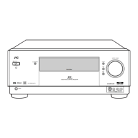
Removing the audio signal 2 board &
video board & s video board
(See Fig.10 to 12)
Prior to performing the following procedure, remove
the top cover and the rear panel.
Disconnect the harness from connector CN973 on
the front AV in board (see Front panel assembly
section/ fig.2).
Cut off the tie band c.
Disconnect the harness from connector CN324 on
the audio signal 2 board.
Disconnect the connector CN321 and CN325. While
removing the claw of the connector CN15, pull out
the audio signal 2 board.
Cut off the tie band d.
Disconnect the card wire from connector CN402 on
the video board.
Pull out the video board upward.
Cut off the tie band e.
Disconnect the card wire from connector CN432 on
the s video board.
Disconnect the connector CN431 on the s video
board. While removing the claw of the connector
CN8, pull out the s video board.
1.
2.
3.
4.
5.
6.
7.
8.
9.
10.
CN221
Fig.10
Fig.11
Video board
CN432
CN431
(connection to CN8)
Tie band e
Tie band d
WR433
Fig.12
Audio signal
2 board
CN325
(connection to CN15)
Audio signal 1 board
Fig.9
CN224
CN223
CN207
CN218
(J/C only)
Plastic rivet
CN321
CN324
WR322
CN402
CN401
S video board
WR403
CN206
Tie band c