RX-DP10VBK/RX-DP10VSL
RX-DP10RSL
1-10
Prior to performing the following procedures, remove
the top cover, rear panel, front panel assembly,
system control board, DSP board, shield cover,
audio signal 1 board, audio signal 2 board, video
board, s video board and input base board.
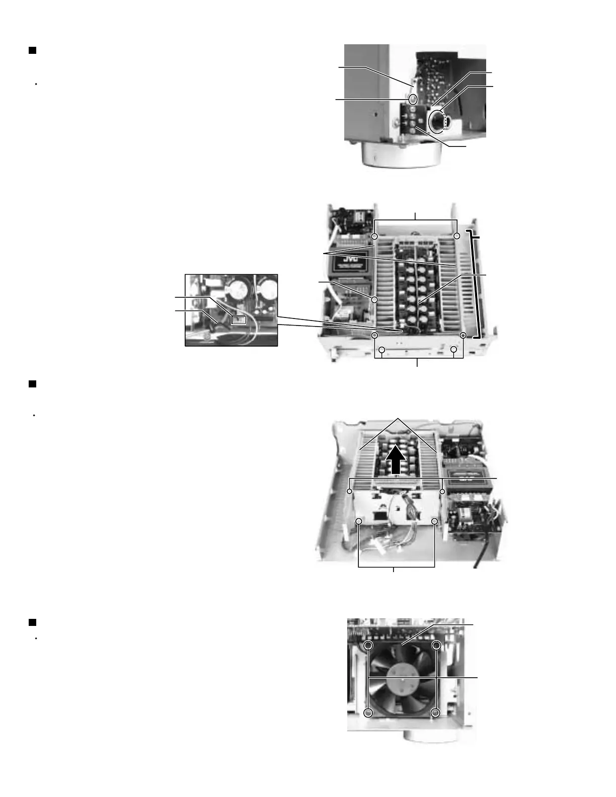
Remove the three screws N fixing the barriers, and
remove the tow barriers.
Remove the eight screws O attaching the power
amp. assembly.
Pull up the power amp. assembly.
1.
2.
3.
Removing the power amp. assembly
(See Fig.21 and 22)
Removing the head phone board
(See Fig.20 and 21)
Prior to performing the following procedures, remove
the top cover, rear panel and front panel assembly.
Disconnect the harnesses from the connector CN981
on the system control board (see fig.5) and CN738
on the power amp. board.
Removing the nut L fixing the head phone board.
Removing the screw M attaching the earth wire and
bracket.
1.
2.
3.
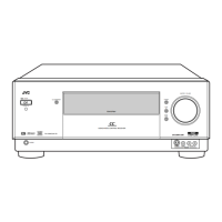
Removing the fan motor (See Fig.23)
Prior to performing the following procedures, remove
the top cover and rear panel.
Disconnect the harness from the connector CN65 on
the power supply 1 board (see fig.16).
Removing the four screws P attaching the fan motor.
1.
2.
Fig.22
Fig.23
(Front side)
Fig.21
Fig.20
N
O
O
P
O
N
M
L
(Rear side)
Power
amp.
assembly
Power
amp.
board
Head phone
board
Barrier
Barrier
Fan motor
CN738
Harness band
Earth wire
Bracket