EasyManua.ls Logo

JVC SP-PW100 - Service Manual

JVC SP-PW100
19 pages
Print Icon
To Next Page IconTo Next Page
Loading...
SERVICE MANUAL
No.21106
May. 2002
COPYRIGHT 2002 VICTOR COMPANY OF JAPAN, LTD.
SP-PW100
POWERED SUBWOOFER
Safety precautions
Disassembly method
Description of major ICs
1- 2
1- 3
1- 7~8
Contents
S
T
A
N
D
B
Y
/
O
N
S
P
-P
W
10
0
P
O
W
E
RE
D
S
U
B
W
O
O
F
E
R
SP-PW100
Area suffix
UP ---------------- Korea

Other manuals for JVC SP-PW100

Question and Answer IconNeed help?

Do you have a question about the JVC SP-PW100 and is the answer not in the manual?

JVC SP-PW100 Specifications

General IconGeneral
Dimensions14.25 x 13.38 x 15.75 inches
Weight33.1 lbs
Enclosure TypeBass Reflex
TypeActive Subwoofer
Power Output100W

Summary

Safety Precautions

Safety Warnings and Precautions

General safety guidelines, warnings, and cautions for product handling and service.

Disassembly Method

Major IC Descriptions

STK411-290 E (IC821) Front Power Amplifier

Details and schematic for the STK411-290E front power amplifier IC.

NJM4580 D (IC811-813) Dual Op-Amp

Pin layout and block diagram for the NJM4580D dual operational amplifier ICs.

TC74 HCU04 AP (IC851) 2 Ch NOR Gate

Pin layout, block diagram, and truth table for the TC74HCU04AP NOR gate IC.

System Diagrams and Circuit Boards

Overall Block Diagram

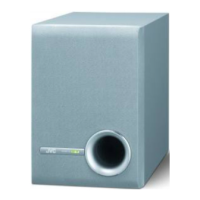
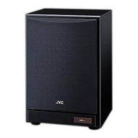
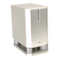
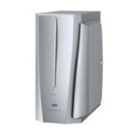
A high-level overview illustrating the JVC SP-PW100 system architecture.

Standard Schematic Diagram

Detailed electrical schematic illustrating the product's circuit design.

Assembly, Parts, and Electrical Lists

Electrical Parts List (Main Board)

List of electrical components used on the main circuit board.

Related product manuals