SP-PW100
1-5
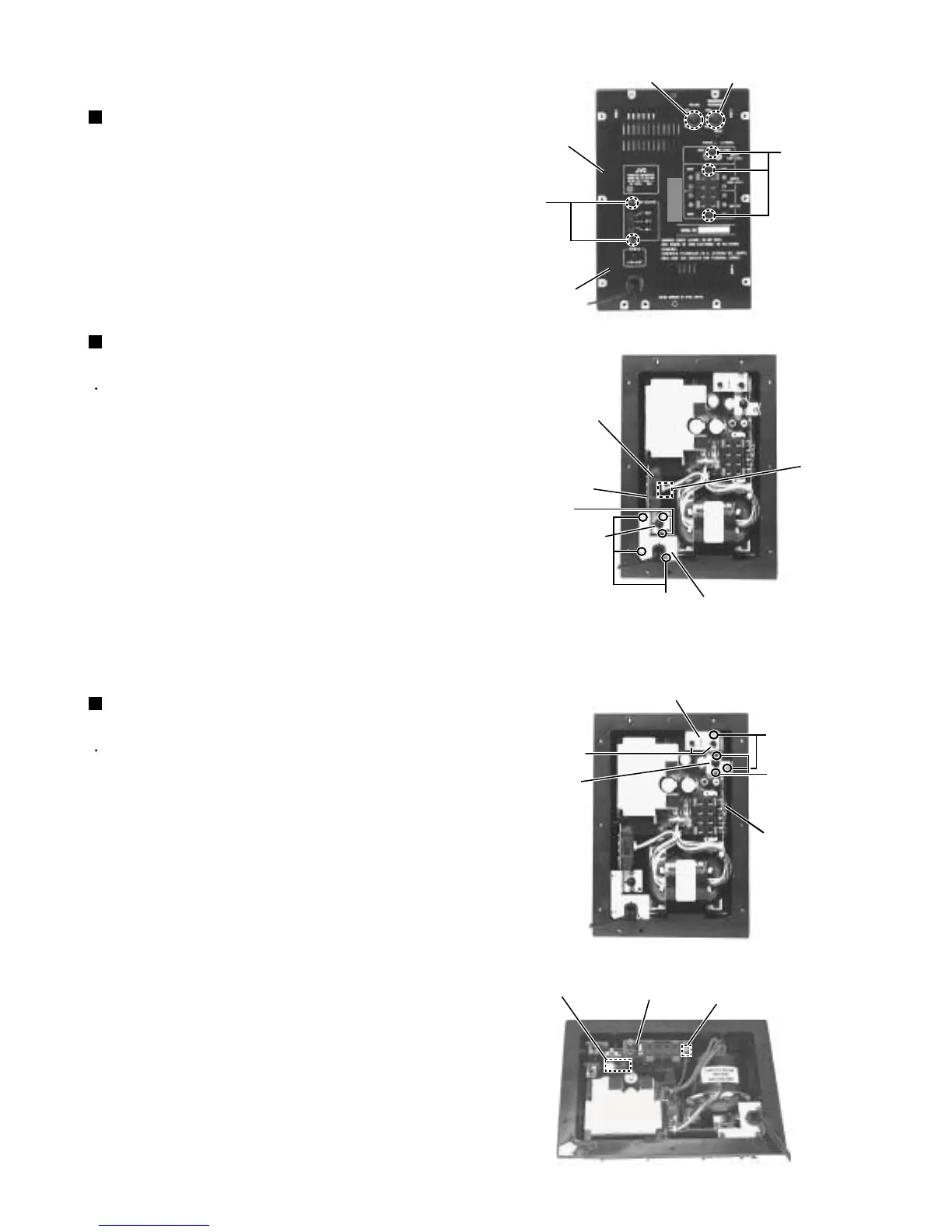
Pull out the volume knob and the crossover
frequency knob.
Remove the three screws D attaching the input jack
and speaker terminal.
Remove the two screws D' attaching the voltage
selector, and then remove the rear panel.
1.
2.
3.
<Amplifier box>
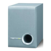
Removing the rear panel (See Fig.9)
Remove the rear panel.
Pull out the power switch knob.
Remove the three screws E and the two screws F
attaching the bracket a.
Pull out the power cord clamp from the bracket a.
Pull out the power switch
board
backward.
Remove the connector CN899.
Note:
1.
2.
3.
4.
5.
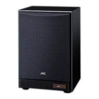
Removing the power switch board
(See Fig.10)
Remove the rear panel.
Pull out the phase knob.
Remove the two nuts attaching the volume knob.
Remove the two screws G and the two screws H
attaching the bracket b.
After removing the connector CN811, pull out the
terminal
board
.
Remove the connector CN851.
1.
2.
3.
4.
5.
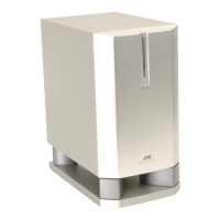
Removing the terminal board
(See Fig.11, 12)
Cut the tie-band, if necessary.
Volume knob
Amplifier box
Rear panel
Nut
Phase knob
Bracket b
Terminal board
CN899
CN811
CN851
Terminal board
Power switch knob
Bracket a
Power switch board
Voltage selector
Crossover frequency knob
D
D'
F
E
G
H
Fig.9
Fig.10
Fig.11
Fig.12