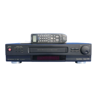
Do you have a question about the JVC SR-S365U and is the answer not in the manual?
Guidelines for safe servicing procedures, including handling of parts and wiring.
Detailed steps for using crimp-type wire connectors safely and correctly.
Verifies insulation resistance between exposed parts and power cord prongs.
Checks dielectric strength between exposed parts and power cord prongs.
Confirms specified clearance between soldered terminals and metallic parts.
Measures leakage current between ground/plug prongs and accessible parts.
Confirms grounding impedance between AC inlet earth pin and exposed parts.
Details specific differences in parts and labels between SR-S365U and SR-S365U(A) models.
Precautions, tape unloading, required tools, and alignment tape specifications.
Identification of main mechanical parts, and procedures for cleaning and lubrication.
Step-by-step instructions for removing and replacing major mechanical components.
Procedures for mounting main mechanism parts with phase adjustment.
Procedures for interchangeability adjustment after part replacement for optimal performance.
Precautions for performing electrical adjustments, requiring proper equipment.
Lists essential test equipment for electrical adjustments.
Lists specific tools needed for electrical adjustments.
Specifies signals like color bars and video sweep for video adjustments.
Adjustment for the 5V DC output voltage of the switching regulator.
Adjustments related to the servo circuit, including PB switching point.
Procedure for automatic and manual adjustment of the PB switching point.
Steps for setting slow tracking for SP, EP, and REV modes to minimize noise.
Overview of video circuit adjustments using the EVR system.
Adjusting the AGC Y level to a specified voltage.
Adjusting white and dark clip levels for S-VHS and VHS modes.
Adjusting the sub emphasis input level.
Adjusting carrier and deviation for S-VHS and VHS signals.
Adjusting the PB Y level for S-VHS and VHS playback.
Adjusting the REC color level for SP and EP modes.
Adjusting S-VHS video equalization for optimal signal.
Adjusting AFC clock for proper video signal timing.
Notes on REC FM level adjustment for the pre/rec circuit.
Procedures for adjusting audio REC FM level and audio EE level.
Adjusting audio record FM level using a sound level meter.
Adjusting audio EE level for optimal sound output.
Adjusting digital I/O level for the Y/C separation circuit.
Procedure for adjusting digital I/O levels for Y/C separation.
A schematic showing the overall wiring connections of the unit.
Schematic diagram for the main SYSCON circuit board.
Schematic diagram for the main servo circuit board.
Schematic diagram for the main video circuit board.
Schematic diagram for the main audio circuit board.
Layout diagram for the main circuit board, showing component placement.
Schematic diagram for the FG AMP circuit board.
Layout diagram for the FG AMP circuit board.
Block diagrams illustrating the function of various ICs used in the unit.
Exploded view of the cabinet and chassis assembly, showing part locations.
Detailed parts list for the cabinet and chassis assembly.
Exploded view of the mechanism assembly, showing part identification and lubrication points.
Detailed parts list for the mechanism assembly.
Explanation of resistor notation and list of common resistor types.
Explanation of capacitor notation and list of common capacitor types.
List of components for the main board assembly, including ICs, diodes, and resistors.
Parts list for FG AMP board assembly, including ICs, diodes, resistors, and capacitors.
| Video System | NTSC |
|---|---|
| Weight | 8.8 lbs |
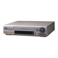
| Type | VCR |
| Heads | 4 |
| Audio | Hi-Fi Stereo |
| Remote Control | Yes |
| Video Format | S-VHS, VHS |
| Recording Speed | SP, LP |