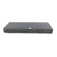
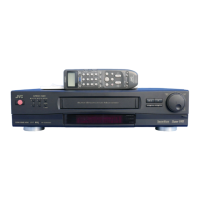
The JVC JX-S100 (EB) is an AV Selector designed to simplify the switching of input signals from various video components, including VCRs, Super VHS camcorders, and other AV source components. Its "passive design" means it requires no external power supply, making it easy to handle and convenient to use.
Function Description:
The JX-S100 (EB) acts as a central hub for managing multiple audio and video sources and directing them to desired output devices. It features four input terminals and two output terminals (one of which is integrated with INPUT-1), along with a dedicated monitor output terminal. This setup allows for flexible connections to Super VHS VCRs, high-resolution TVs, and other Super VHS compatible video components. The device supports both S-VIDEO and composite video signals, with S-VIDEO having priority over composite video for INPUT-4 terminals. A key feature is the DUBBING mode, which facilitates video editing and copying between connected VCRs.
Important Technical Specifications:
- Inputs: 4 lines (Super VHS compatible).
- Outputs: 2 lines (Super VHS compatible, 1 line included in INPUT-1).
- Monitor Output: 1 line (Super VHS compatible).
- Frequency Response:
- Video: 0-10 MHz.
- Audio: 0-100 kHz.
- Dimensions (W x H x D): 435 mm x 47 mm x 165.5 mm (including knobs and feet).
- Weight: 1.5 kg.
- Power: Passive design (no external power supply required).
Usage Features:
- Input Select Buttons: These front-panel buttons allow users to easily select the desired input source from the four available lines.
- DUBBING Button: Pressing this button engages the dubbing/editing mode, with the signal flow clearly indicated beneath each input select button. This simplifies the process of copying content between two VCRs.
- Front Panel Input-4 Terminals: Conveniently located on the front panel, these terminals are ideal for temporary hook-ups of devices like camcorders or portable VCRs, supporting S-VIDEO, video, and L/R audio connections.
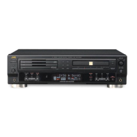
- Rear Panel Connectivity: The rear panel offers comprehensive connectivity for permanent installations, including:
- MONITOR OUTPUT Terminal: Connects to the input terminals of a monitor TV.
- OUTPUT-1 Terminal: Connects to the input terminals of video/audio components.
- INPUT-2/-3 Terminals: Connects to the output terminals of video/audio components.
- INPUT-1/OUTPUT-1 Terminal: Connects to the input/output terminals of video/audio components, supporting Super VHS compatible connections.
- Flexible VCR Connections: The manual details two primary ways to connect VCRs:
- Using two separate cables for INPUT-1/OUTPUT-1 and OUTPUT-1 for Super VHS compatible components.
- Using one cable for INPUT-1/OUTPUT-1.
- Camcorder (VideoMovie) Connections: Supports both stereo and monaural audio outputs from camcorders, with S-VIDEO and composite video options.
- A/V Control (Slow SW) Function Compatibility: INPUT-1 through INPUT-3 terminals are compatible with A/V control (Slow SW) function, ensuring that the video signal from a connected VCR with this function is automatically selected regardless of the monitor TV's video input mode.
- Troubleshooting Guide: The manual includes a comprehensive troubleshooting section to address common issues such as no picture, distorted picture/sound, or recording problems, providing causes and remedies.
Maintenance Features:
- Disassembly Instructions: Detailed steps are provided for disassembling the unit, including removing the top cover, front panel, and PC board assembly. This information is crucial for service and repair.
- Removing the Top Cover: Involves removing five screws and gently lifting the cover towards the rear.
- Removing the Front Panel: Requires removing five screws after the top cover is off, then gently pulling the front panel forward.
- Removing the PC Board Assembly: After the top cover and front panel are removed, three screws retaining the PC board assembly and ten screws fixing the jacks to the chassis need to be removed.
- Main Parts Locations: An exploded view and a diagram showing the main parts locations (e.g., Push Switch, Front Panel, 4-Push Switch, P.C. Board Ass'y, 21P-Connector, Chassis) are provided to aid in identification and replacement during maintenance.
- Parts List: A detailed list of electric and mechanical parts, including symbol numbers, part numbers, part names, quantities, and remarks (e.g., Gold-Plated, Yellow, White, Red for jacks), is included. This list also notes that P.C. Boards are not supplied as assemblies.
- Schematic Diagram: A standard circuit diagram is provided, illustrating the internal wiring and connections, which is essential for diagnosing electrical issues.
- Printed Circuit Board Layout: A diagram of the printed circuit board, indicating ground and other voltage areas, is included to assist in component identification and circuit tracing.
- Packing Materials and Accessories Lists: These lists ensure that all components are accounted for during shipping and installation, and provide details on included accessories like instruction books and EEC agency information.
The JX-S100 (EB) is designed for ease of use and robust performance, making it a reliable AV selector for various home entertainment setups.