2-27
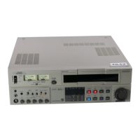
<Note 4a>: When attaching this part, fit it in the boss (L7)
on the charge arm assembly.
<Note 4b>: When attaching or removing this part, take care
of the handling of the band section.
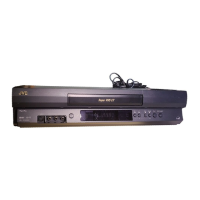
<Note 4c>: After fitting the spring on the shaft, engage it with
hook a first then with hook b .
After attaching it, set it to the positioning shown
in “Step 3” and confirm that band arm plate sub
assembly 7 can be rotated in the direction of
the arrow as shown below.
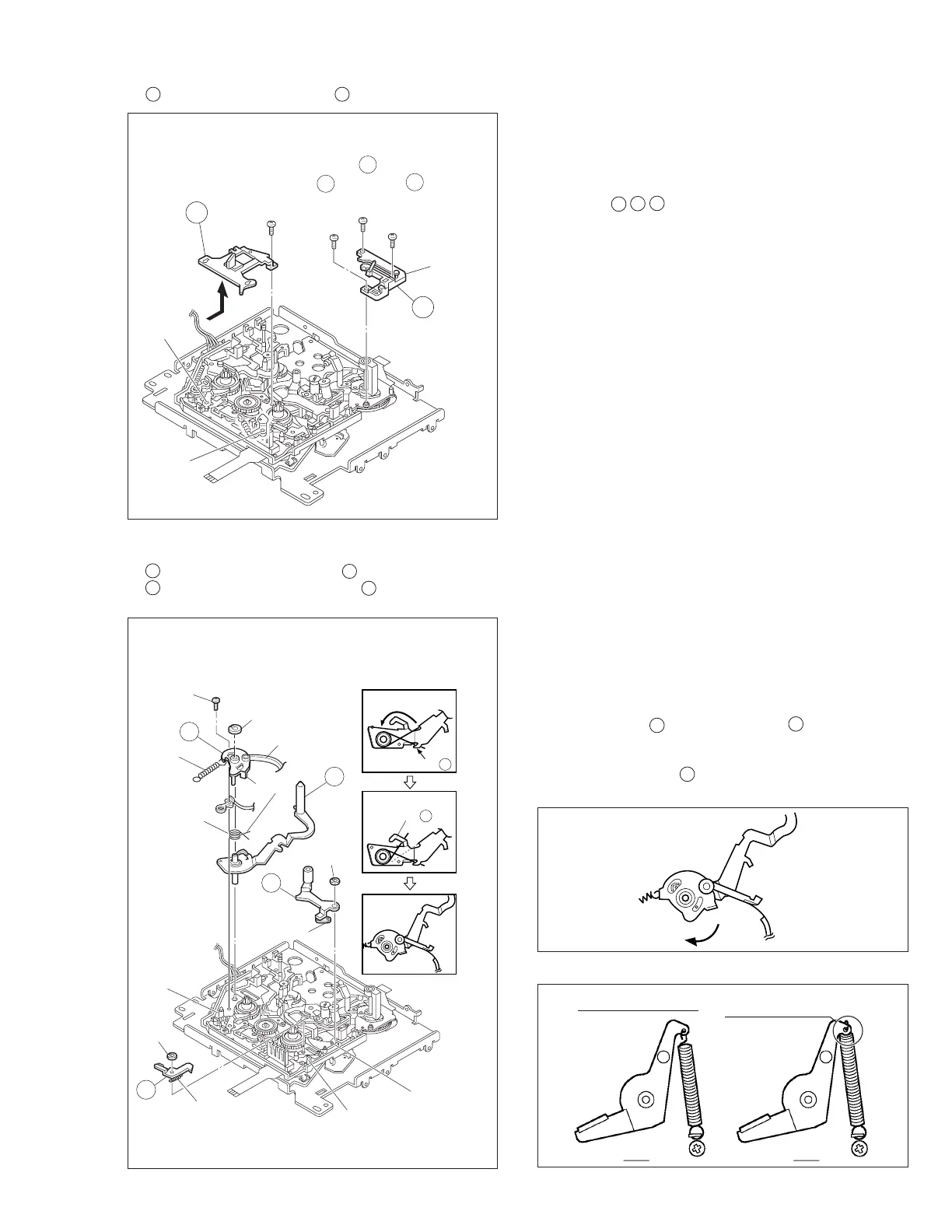
3. 3
Middle Catcher Assembly/
4 Reel Cover Assembly
Fig. 2-8-3
Fig. 2-8-4
3
13
(
S2
)
(
L6
)
(
L6
)
4
<Note3a>
a
b
c
Apply grease
12
(
S2
)
<Note3b>
10
(
S2
)
<Note3b>
11
(
S2
)
<Note3b>
4.
5 Pinch Roller Arm Assembly/ 6 Sub Brake Assembly/
7 Band Arm Plate Sub Assembly/ 8 Tension Arm Sub
Assembly
5
7
8
(
W1
)
(
W2
)
14
(
S3
)
(
P2
)
(
L9
)
(
L7
)
(
L8
)
(
W1
)
6
(
P1
)
(
P3
)
<Note 4c>:
How to install the spring
<Note4a>
<Note4b>
NOTE4c
Step 1
Step 2
Step 3
Hook a
Hook b
Fig. 2-8-4A
<Note 3a>: Once the reel cover assembly has been re-
moved, the parts located below it tend to slip out
easily: Be careful.
<Note 3b>: When attaching these screws, screwing order
a b c .
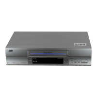
Fig. 2-8-4B
SUB BRAKE(T)
OK NG
SPRING HOOKED
REVERSE-SIDE