2-28
5.
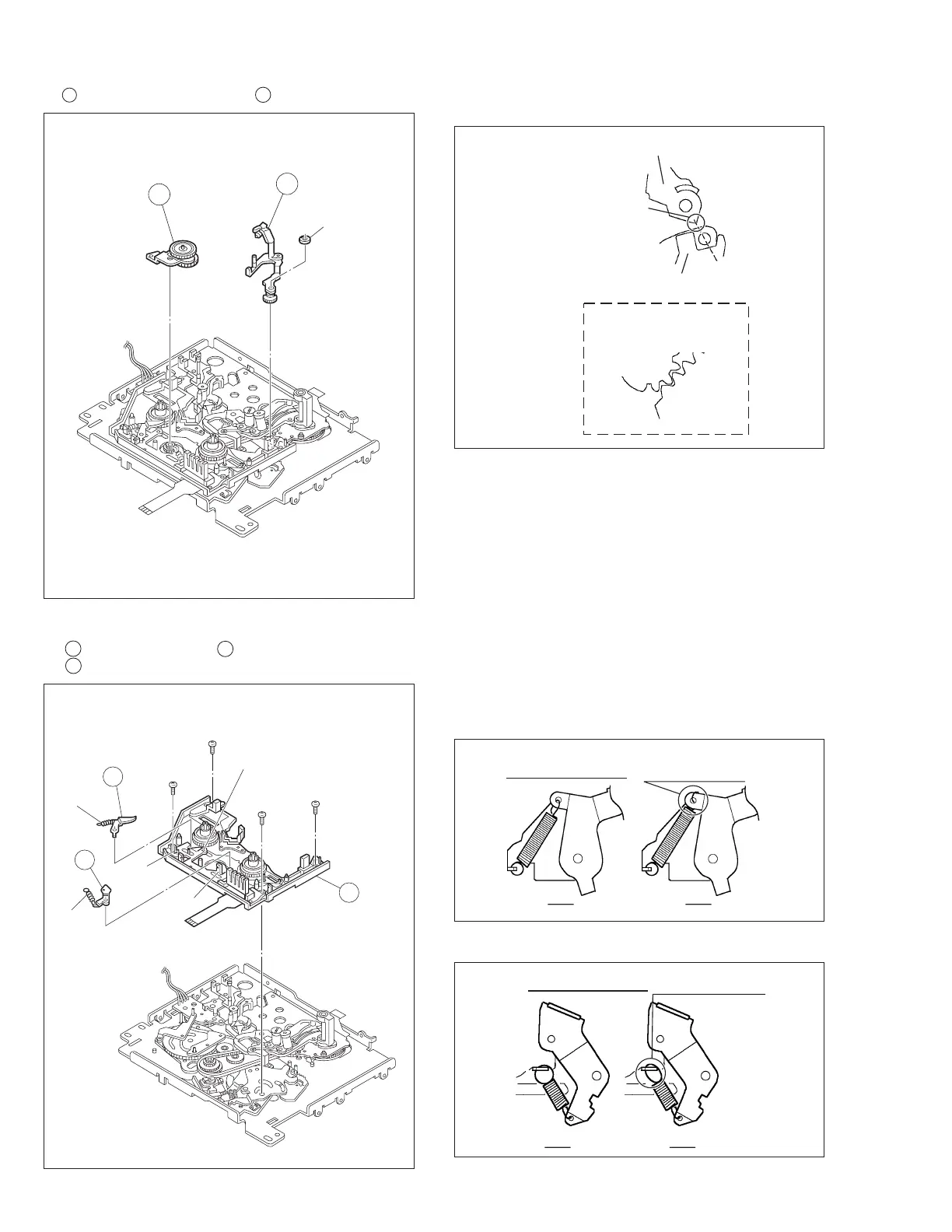
9 EXIT Guide Arm Assembly/ 10 Swing Arm Assembly
Fig. 2-8-5
Fig. 2-8-6
<Note 6a>: When attaching the sub deck assembly, make
sure to adjust the phase of the control plate.
6.
11 Sub Deck Assembly/ 12 Main Brake (Sup) Assembly/
13 Main Brake (Take up) Assembly
(
W1
)
10
9
<Note5a>
13
12
11
18
(
S2
)
15
(
S2
)
16
(
S2
)
17
(
S2
)
(
L10
)
(
L11
)
(
P4
)
(
P5
)
<Note6a>
Fig. 2-8-5A
EXIT Guide Arm Assembly
Charge Arm Assembly
Gear alignment
EXIT Guide Arm
Assembly
Arm Gear 2
Assembly
This protrusion is
combined to
the dent of CHARGE
ARM ASS'Y.
<Note 5a>: EXIT Guide Arm Assembly phase alignment.
MAIN BRAKE(S)
OK NG
SPRING HOOKED
REVERSE-SIDE
Fig. 2-8-6A
Fig. 2-8-6B
MAIN BRAKE(T)
OK NG
TWISTED SPRING