2-29
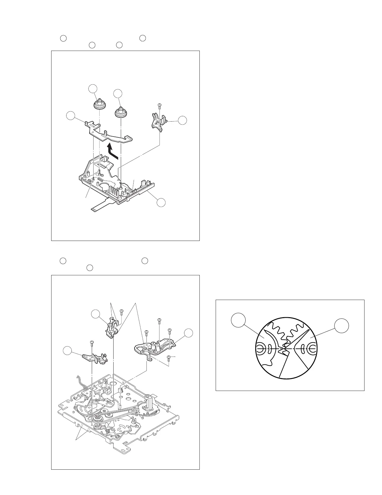
Fig. 2-8-7
Fig. 2-8-8
<Note 8a>: When attaching, set the alignment markings of
the two gears so that the markings face oppo-
site to each other.
8.
18 Guide rail (Take up) assembly / 19 Guide rail (Sup)
assembly / 20 Base plate assembly
14
(
L12
)
(
L12
)
17
15
16
11
19
(
S2
)
25
(
S2
)
20
19
20
(
S2
)
21
(
S2
)
24
(
S2
)
22
(
S2
)
18
23
(
S2
)
(
L13
)
(
L14
)
<Note8a>
Fig. 2-8-8A
7.
14 Reel disk assembly (Sup) / 15 Reel disk assembly
(Take up) / 16 Prism / 17 Control plate