2-30
9.
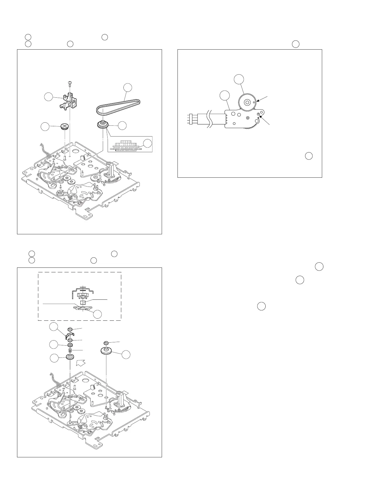
21
Ent. guide base assembly /
22
Worm wheel 2 /
23
Timing belt /
24
Center gear assembly
Fig. 2-8-9
Fig. 2-8-10
<Note 9a>: How to attach the worm wheel 2 22 .
10.
25
Reel drive pulley assembly
/
26
Push plate
27
Clutch lock gear(2)
/
28
Clutch lock gear (1)
Fig. 2-8-9A
Align the phase of the rotary encoder assembly 34 ,
then attach it by aligning the phase hole of the mecha-
nism assembly.
26
(
S2
)
21
22
24
23
23
<Note9a>
27
(
W1
)
(
W3
)
(
P6
)
28
26
(
W1
)
25
"A"
<Note10a>
DETAIL "A"
FLANGE
(P6)
28
<Note10b>
34
22
Phase alignment
Mark (Red)
<Note 10a>: After attaching (W1), confirm that pushes 26
from the top and hit to MAIN DECK.
If there are a rattling or inclination in 26 , recon-
firm the attachment of (P6).
(Take care to the oblique insertion of (P6).)
<Note 10b>: Attach (P6) straight for it which does not get
on on the flange of 28 .