(No.MB082)1-7
3.3 Removing the power cord
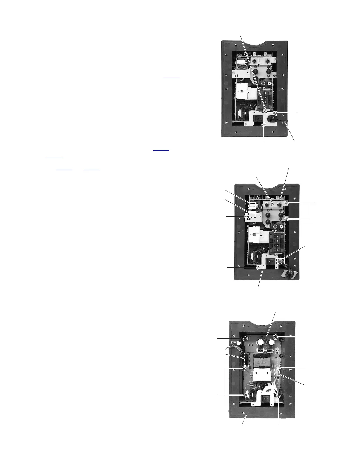
(See Figs.4 and 5)
• Prior to performing the following procedures, remove the back
panel.
(1) Remove the two screw C attaching the bracket (CORD).
(See Fig.4.)
(2) Take out the bracket (CORD) toward this side.
(3) Disconnect the power cord from the connector CN901
.
(See Fig.5.)
3.4 Removing the amplifier board assembly
(See Figs.5 and 6)
• Prior to performing the following procedures, remove the back
panel and power cord.
(1) Remove the screw D attaching the bracket (SW). (See
Fig.5.)
(2) Remove the three screws E attaching the bracket (KNOB).
(See Fig.5.)
(3) Disconnect the wires from the connecters CN102
and
CN503
. (See Fig.5.)
(4) Disconnect the amplifier board assembly from the connec-
tors CN951
and CN952 on the regulator board. (See Fig.6.)
(5) Take out the amplifier board assembly from the amplifier
assembly.
3.5 Removing the regulator board
(See Fig.6)
• Prior to performing the following procedures, remove the back
panel, power cord and amplifier board assembly.
(1) Remove the two screws F and four screws G attaching the
regulator board.
(2) Take out the regulator board from the cover.
Fig.4
Fig.5
Fig.6
Bracket (CORD)
C
Power cord
C
Amplifier board assembly
E
CN901
E
D
CN503
CN102
Bracket (SW)
Bracket (KNOB)
CN951
CN952
F
F
Regulator board
G
G
Cover
G
www.freeservicemanuals.info
 Loading...