EasyManua.ls Logo

JVC TD-V711 Service Manual

JVC TD-V711
31 pages
To Next Page IconTo Next Page
Page #1 background imageLoading...
Page #1 background image
TD-V711
A/B/C/E/G/J/
_
SERVICE
MANUAL
Contents
Page
Page
[1]
Safety
Precautions
....0..0.ccccccccceeseseteerreee
2
[10]
Location
of
P.C.
Board
Parts
and
Parts
List
Specifications
........c0.ccccccceeeeee
ap
edi
aks
ateeas
3
Main:
Bat
ect
22
ccc
ace
steric
bacesecamselelaesteiateans
16
[3]
Location
of
Main
Parts
.......
iezivdead
¢
visas
oeseh
Cente
vase
4
Power
Supply/Mechanism
Control
...............5..
20
[4]
Location
of
Control
.........
saaggetagas
eee
ES
[14]
Exploded
View
of
Mechanism
Assembly
Parts
Removal
of
Main
Parts
...............
wiedcghs
pee
wu
and:
Parts:
Listisi
So.
sfeccuectsycudidda
ee
Sui
Sh
oe
ts
22
[6]
ACJUStMENt
20...
..ccc
ccc
cccececcecncccsencaucecnccscnreusecs
ew
[12]
Exploded
View
of
Enclosure
Assembly
Parts
[7]
Block
Diagram
......ccccccccccccccssecesseseesecesevssecsvese
12
and
Parts
List
.............
cece
Ledisaantet
totes:
24
[8]
Wiring
oo...
cece
‘ggasasanee
ges
aeChectonctsssa
13
[13}
Packing”
s..c.icscccssssscsssecssssesecvscsserensevseveceereeteess
28
[9]
Standard
Schematic
Diagram
.............0.....
wegen
4
[14]
ACCOSSONES
is.
sonic
Ai
Seis
sasseatieeaas
certian
ooadadasee
ed
No.
4294
March
1988
Question and Answer IconNeed help?

Do you have a question about the JVC TD-V711 and is the answer not in the manual?

JVC TD-V711 Specifications

General IconGeneral
BrandJVC
ModelTD-V711
CategoryCassette Player
LanguageEnglish

Summary

Safety Precautions

Warning

Safety notices and repairer responsibilities.

Specifications

Location of Main Parts

Location of Controls

Removal of Main Parts

Cabinet and Front Panel Removal

Steps for removing cabinet covers and front panel assembly.

Mechanism and Internal Component Removal

Procedures for removing the mechanism, motors, and switches.

Main Adjustment

Required Measuring Instruments

List of tools needed for calibration and adjustments.

Mechanical Adjustment Procedures

Steps for physical alignment of mechanical parts.

Head Position and Door Safety

Adjusting head position and checking door safety mechanisms.

Block Diagram

Wiring Connections

Standard Schematic Diagram

Parts Lists and Diagrams

P.C. Board Parts List

Detailed list of components for printed circuit boards.

Power Supply/Mechanism Control Board Parts List

Component list for the power supply and mechanism control board.

Mechanism Assembly Exploded View

Visual breakdown of the mechanism with parts identification.

Enclosure Assembly Exploded View

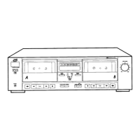
Visual breakdown of the unit's enclosure with parts identification.

Packing

Accessories

Related product manuals