(No.MB638)1-17
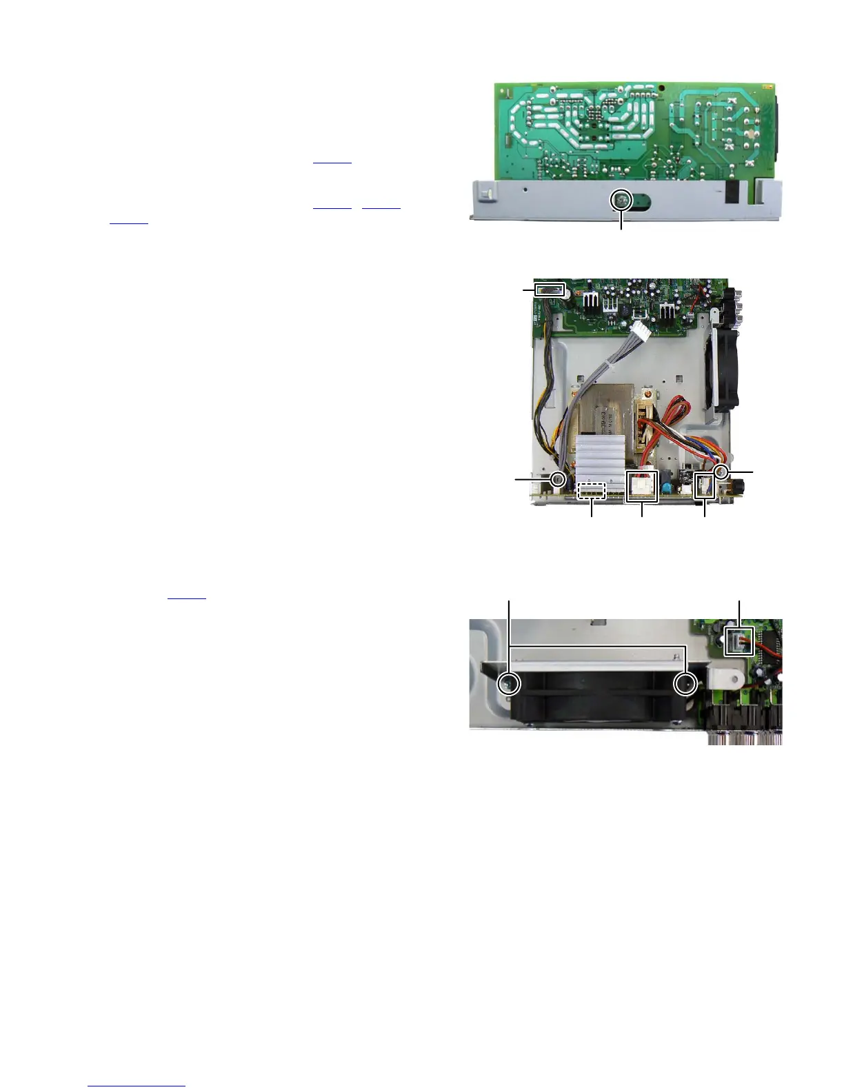
3.1.10 Removing the POWER BOARD assembly (See Fig.18, 19)
(1) Remove the one screw S attaching the POWER BOARD
assembly. (See Fig.18)
(2) Remove the two screws T attaching the BRACKET. (See
Fig.19)
(3)
Disconnect the connector wire from POWER BOARD
assembly connected to connector
CN151
of the MAIN
BOARD assembly. (See Fig.
19
)
(4) Disconnect the connector wires from POWER TRANS-
FORMER connected to connector CN102
, CN103 and
CN104 of the POWER BOARD assembly. (See Fig.19)
Fig.18
Fig.19
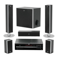
3.1.11 Removing the FAN (See Fig.20)
(1) Disconnect the connector wire from the FAN connected to
connector CN152
of the MAIN BOARD assembly.
(2) Remove the two screws U attaching the FAN.
Fig.20
S
T
T
CN151
CN104 CN103 CN102
CN152
U