1-10 (No.MB393)
3.1.2 Removing the front panel assembly
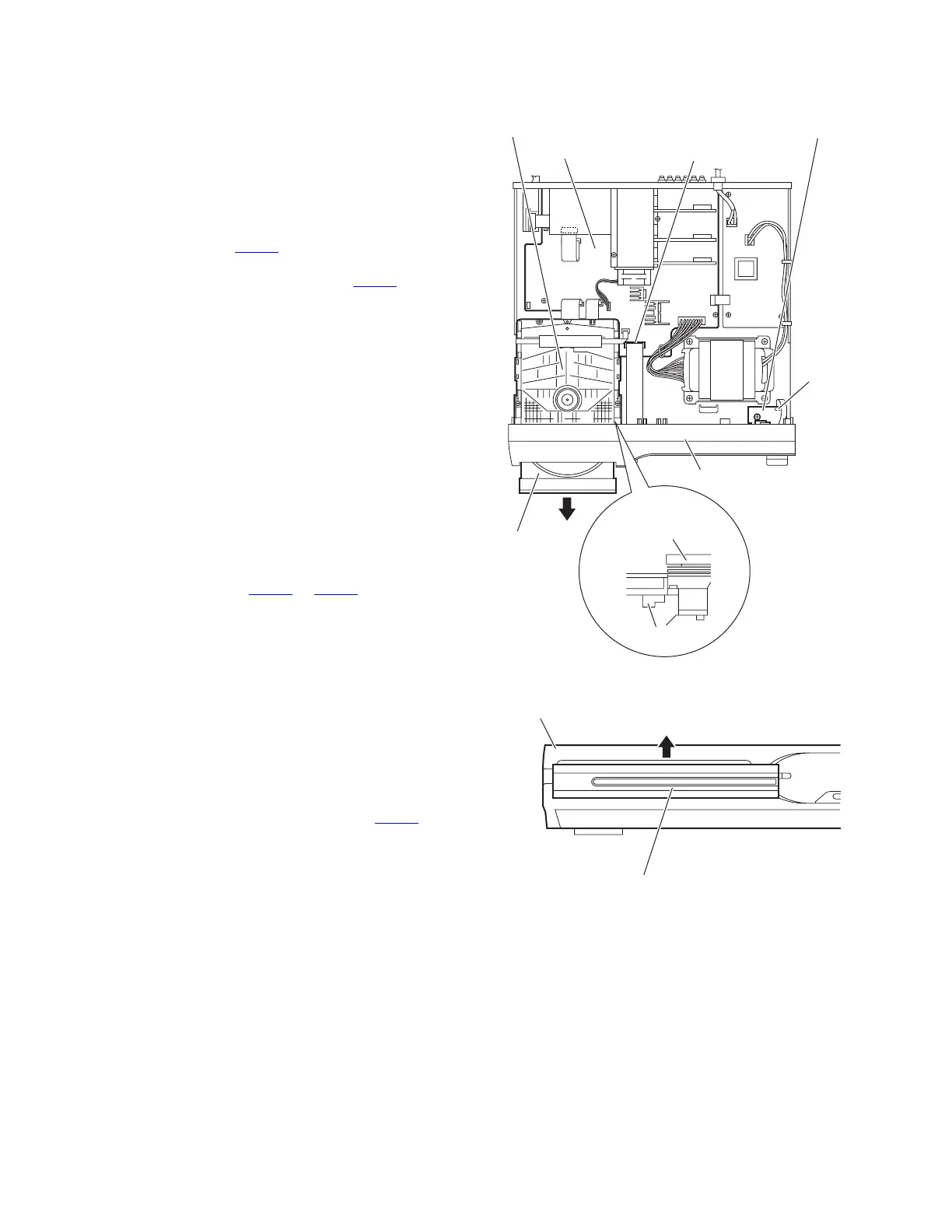
(See Figs.5 to 7)
• Remove the metal cover.
(1) From the right side of the DVD mechanism assembly, push
the slide cam and pull the tray assembly out of the main
body in the direction of the arrow. (See Fig.5.)
(2) From the front side of the main body, remove the CD fitting
assembly from the tray assembly in the direction of the ar-
row and push in the tray assembly as before. (See Fig.6.)
(3) From the top side of the main body, disconnect the card
wire from the connector CN400
on the main board. (See
Fig.5.)
(4) Disconnect the card wire from the connector CN510
on the
HP terminal board. (See Fig.5.)
(5) From the bottom side of the main body, remove the three
screws C attaching the front panel assembly. (See Fig.7.)
(6) From both sides and back side of the main body, remove
the front panel assembly in the direction of the arrow while
releasing the joints b. (See Fig.7.)
3.1.3 Removing the DVD mechanism assembly
(See Figs.5,6 and 8)
• Remove the metal cover.
(1) From the right side of the DVD mechanism assembly, push
the slide cam and pull the tray assembly out of the main
body in the direction of the arrow. (See Fig.5.)
(2) From the front side of the main body, remove the CD fitting
from the tray assembly in the direction of the arrow and
push in the tray assembly as before. (See Fig.6.)
(3) From the top side of the main body, disconnect the card
wires from the connectors CN403
to CN405 on the main
board. (See Fig.8.)
(4) Remove the three screws D attaching the DVD mechanism
assembly to the chassis base. (See Fig.8.)
3.1.4 Removing the HP terminal board
(See Fig.8)
• Remove the metal cover.
Reference:
Remove the front panel assembly as required. (See 3.1.2 "Re-
moving the front panel assembly".)
(1) From the top side of the main body, remove the screw E at-
taching the HP terminal board to the chassis base.
(2) Disconnect the card wires from the connectors CN510
on
the HP terminal board. (See Fig.8.)
(3) Take out the HP terminal board from the main body.
Reference:
When attaching the HP terminal board, align the hole on the
HP terminal board to the projection c of the chassis base be-
fore attaching the screw E.
Fig.5
Fig.6
Slide cam
DVD mechanism
assembly
Tray assembly
Front panel assembly
CN510
HP terminal board
CN400
Main board
DVD mechanism assembly
Front panel assembly
CD fitting assembly
 Loading...