(No.MB260)1-23
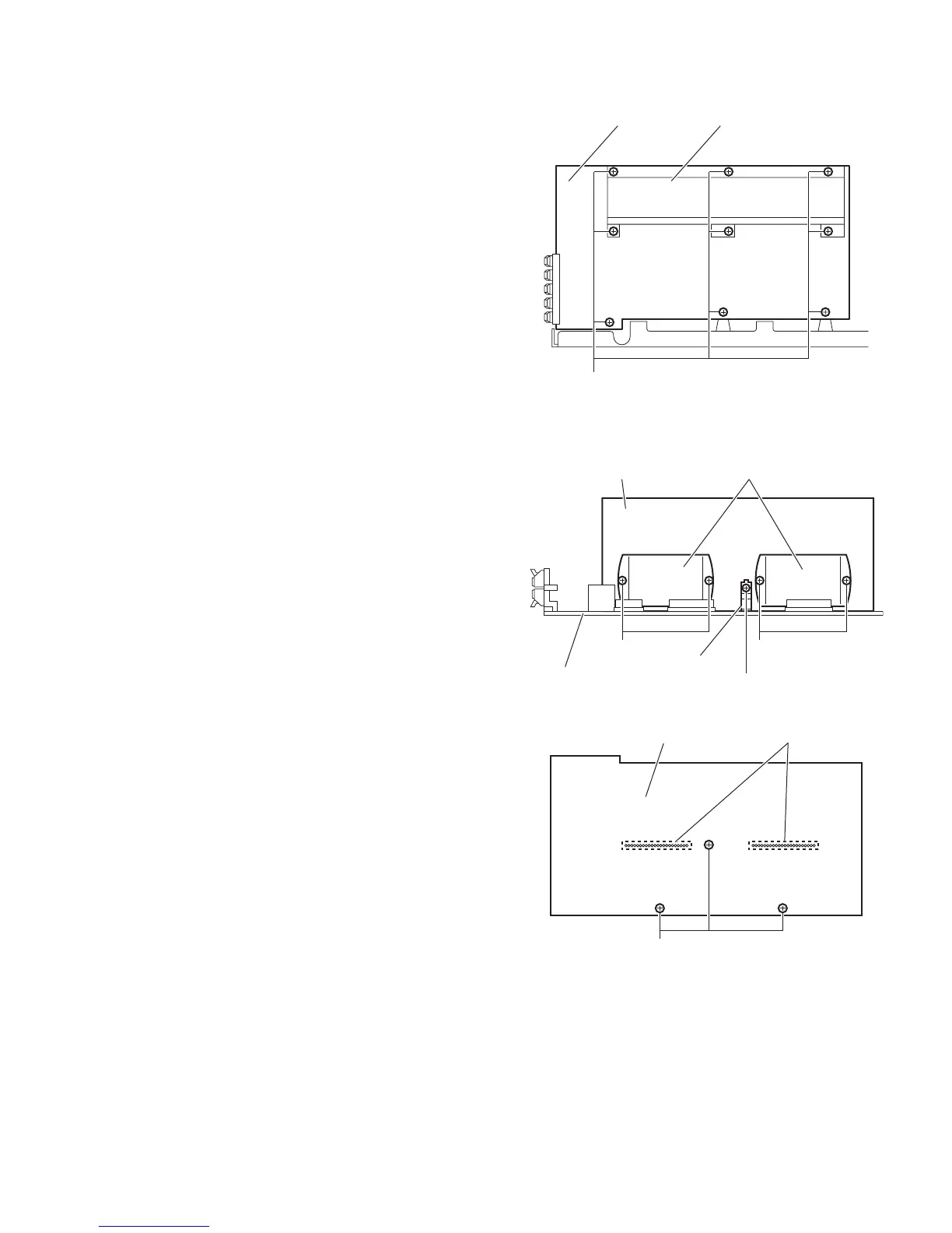
3.4.6 Removing the amp. board
(See Fig.10)
• Prior to performing the following procedures, remove the am-
plifier assembly, rear panel, heat sink BKT and mother board.
(1) From the left side of the amplifier assembly, remove the
nine screws J attaching the amp. board.
(2) Take out the amp. board with the heat sink.
Fig.10
3.4.7 Removing the heat sink
(See Figs.11 and 12)
• Prior to performing the following procedures, remove the am-
plifier assembly, rear panel, heat sink BKT, mother board and
amp. board.
(1) From left side of the amp. board, remove the screw K at-
taching the hold spring to the heat sink. (See Fig.11)
(2) Remove the four screws L attaching the power IC to the
heat sink. (See Fig.11)
(3) From the reverse side of the amp. board, remove the three
screws M attaching the heat sink to the amp. board. (See
Fig.12)
(4) Take out the heat sink.
3.4.8 Removing the power IC
(See Fig. 12)
• Prior to performing the following procedures, remove the am-
plifier assembly, rear panel, heat sink BKT, mother board,
amp. board and heat sink.
(1) From the reverse side of the amp. board, remove the sol-
ders from the solder points a on the amp. board.
(2) Take out the power IC.
Fig.11
Fig.12
Amp. board
J
Heat sink
Amp. board
Hold spring
Power ICHeat sink
L L
K
Amp. board Solder points a
M
 Loading...