No. 51961
TM-H1950CG
35
Item Test equipment Test points
Ad ju st men t
locations
Ad justment procedure
4:3
Under scan
Hor izo nt a l
ce nter
Ad ju st men t
Signal generator
(Circle pattern)
DD01 (H. CENTER)
[SERVICE MENU]
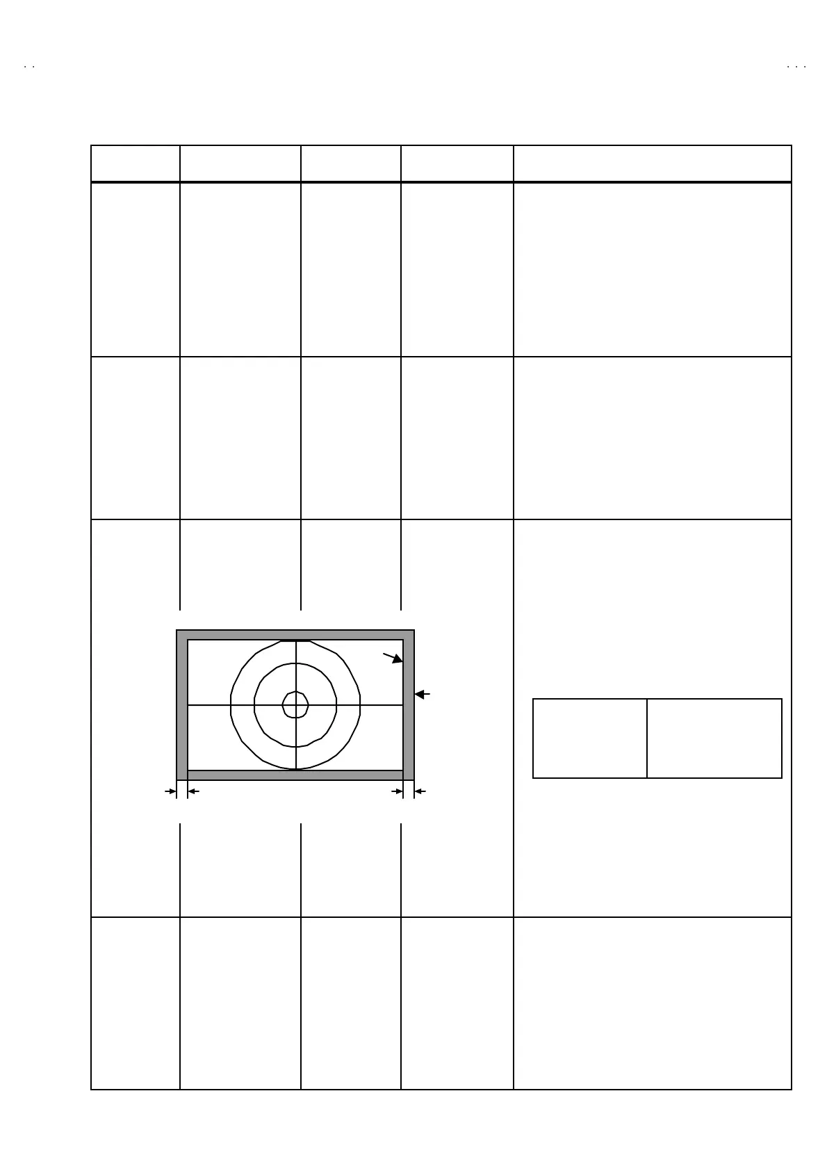
23 . Switch the asp ect ratio t o t he 4: 3 mode.
24 . Inp ut th e PA L c ircle pat ter n sign al.
25 . Se lect t he un der sc an mod e.
26 . Select th e DD0 1 a nd adju st it t o th e lef t an d rig ht
bla nking wid th bec ome e qu al.
4:3
Under scan
Side
pincushion
Ad ju st men t
Signal generator
(Crosshatch pattern)
DD07
E-W PARABORA
DD08
(E-W CORNER)
[SERVICE MENU]
27 . Conf irm t he sid e pinc ushio n of the f our corner s in
th e scre en.
28 . If n ot op timu m, ad just th e DD0 7 an d DD0 8 to
become c orrec tly.
4:3
Under scan
Hor izo nt a l
siz e
Ad ju st men t
Signal generator
(Crosshatch pattern)
DD02(H. SIZE)
C22(TRAPEZOI D)
DD01
H. CENTER
[SERVICE MENU]
29 . Select th e DD0 2 a nd adju st it t o th e lef t an d rig ht
bla nking widths be come t he value give n b elow.
30. At this t ime, it c hec ks that c orner of the screen is
not distorted. If distorted, adjust the C22 to
become c orrec t.
31 . If horizon tal c ent er is shift ed, read just DD01 .
16 :9
Under scan
Side
pincushion
Ad ju st men t
Signal generator
(Crosshatch pattern)
DF 07
E-W PARABORA
DF 08
(E-W CORNER)
[SERVICE MENU]
32 . Switch the asp ect ratio t o t he 16 :9 mode.
33 . Conf irm t he sid e pinc ushio n of the f our corner s in
th e scre en.
34 . If n ot op timu m, adju st the DF0 7 an d DF08 to
become c orrec tly.
35. Turn the scan size to the normal.
Hor izo nt a l
Blanking Width
(one side of screen)
7~
~~
~ 10 mm
7
~
10mm
PICTURE
SIZE
E ffe ctive
sc reen si ze
7
~
10mm

 Loading...