UX-J50
1-12 (No.22032)
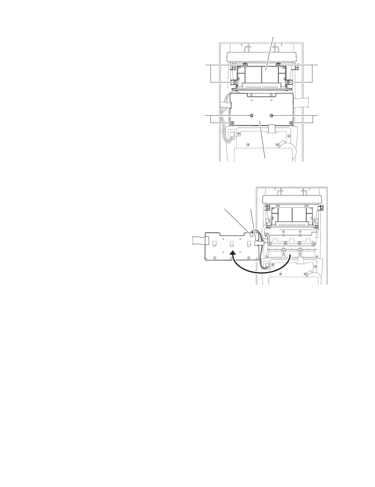
2.1.11 Removing the switch board
(See Fig.17,18)
• Prior to performing the following procedure, remove the metal
cover and the front panel assembly.
(1) Remove the four screws M attaching the switch board.
(2) Move the switch board in the direction of the arrow to dis-
connect the wire from the connector CN762 and the card
wire from the connector CN761.
2.1.12 Remove the LCD board assembly
(See Fig.17)
• Prior to performing the following procedure, remove the metal
cover and the front panel assembly.
(1) Remove the four screws N attaching the LCD board as-
sembly.
Fig.17
Fig.18
M
NN
M
Switch board
LCD board assembly
Switch board
CN762 CN761
 Loading...