UX-M3R
1-23
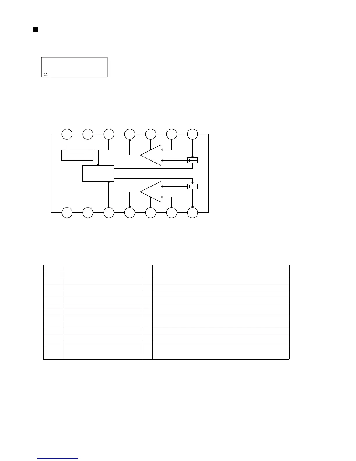
AN7312 (IC202) : Dual recording/Playback pre-amplifier circuit with ALC
1. Terminal layout
3. Pin function
2. Block diagram
17
Pin No.
Symbol
I/O
Function
~
14 8
~
GND
ALC time constant
ALC input Ch.1
Output Ch.1
Phase compensation Ch.1
N.E.B. Ch.1
Input Ch.1
Input Ch.2
N.E.B. Ch.2
Phase compensation Ch.2
Output Ch.2
ALC input Ch.2
Ripple filter
Vcc
1
2
3
4
5
6
7
8
9
10
11
12
13
14
-
-
I
O
-
I
I
I
I
-
O
I
-
-
GND
ALC time constant by resistance and capacitor
Right channel ALC input
Right channel output
No connect
Right channel negative feed back input
Right channel signal input
Left channel signal input
Left channel negative feed back input
No connect
Left channel output
Left channel ALC input
Ripple filter
Power supply
14 13 12 11 10 9
1 2 3 4 5 6
Ripple Filter
Amp.
Ch2
8
ALC
7
GND
Vcc
Amp.
Ch1
 Loading...