UX-M3R
1-27
GND
L-IN1
L-IN2
L-IN3
L-IN4
L SW-OUT
L VR-IN
L-B1
L-B2
L-B3
L TONE-OUT
L-T1
Vref
CK
DATA
STB
R-T1
R TONE-OUT
R-B3
R-B2
R-B1
R VR-IN
R SW-OUT
R-IN4
R-IN3
R-IN2
R-IN1
VDD
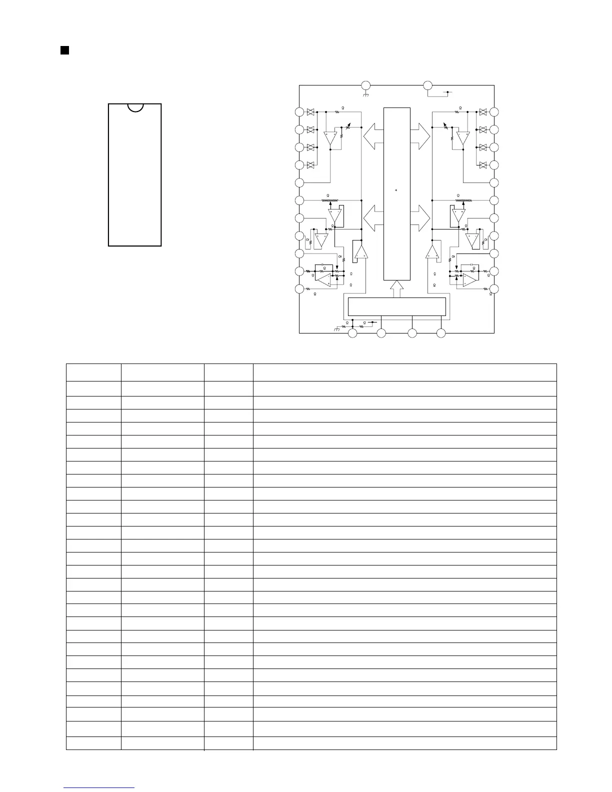
Pin No.
Symbol I/O Function
1
2
3
4
5
6
7
8
9
10
11
12
13
14
15
16
17
18
19
20
21
22
23
24
25
26
27
28
Ground pin
Audio signal input pin (L-ch)
Audio signal input pin (L-ch)
Audio signal input pin (L-ch)
Audio signal input pin (L-ch)
Audio signal output pin (L-ch)
Main volume input pin (L-ch)
Tone control tap pin 1 for bus
Tone control tap pin 2 for bus
Tone control tap pin 3 for bus
Tone control output pin (L-ch)
Tone control tap pin for treble (L-ch)
Reference voltage input pin
Clock input pin
Data input pin
Strobe input pin
Tone control tap pin for treble (R-ch)
Tone control output pin (R-ch)
Tone control tap pin 3 for bus
Tone control tap pin 2 for bus
Tone control tap pin 1 for bus
Main volume input pin (R-ch)
Audio signal output pin (R-ch)
Audio signal input pin (R-ch)
Audio signal input pin (R-ch)
Audio signal input pin (R-ch)
Audio signal input pin (R-ch)
Power supply voltage pin
-
I
I
I
I
O
I
I
I
I
O
I
I
I
I
I
I
O
I
I
I
I
O
I
I
I
I
-
3.Pin Function
GND
L-IN1
L-IN2
L-IN3
L-IN4
L SW-OUT
L VR-IN
L-B1
L-B2
L-B3
L TONE-OUT
L-T1
Vref
CK
VDD
R-IN1
R-IN2
R-IN3
R-IN4
R SW-OUT
R VR-IN
R-B1
R-B2
R-B3
R TONE-OUT
R-T1
STB
DATA
28
27
26
25
24
23
22
21
20
19
18
17
16
15
1
2
3
4
5
6
7
8
9
10
11
12
13
14
1.Terminal Layout 2.Block Diagram
TC9422F (IC301) : System electronic volume
281
1613 14 15
5
3
4
2
24
23
22
21
20
19
18
17
26
25
27
LATCH
DECODER
CIRCUIT
32BIT SR
GND VDD
L-IN1
L-IN2
L-IN3
L-IN4
Vref CK DATA STB
R-T1
R Tone-OUT
R-B3
R-B2
R-B1
R VR-IN
R SW-OUT
R-IN4
R-IN3
R-IN2
R-IN1
INPUT SELECTOR
100k
MAIN VR
50k /64STEP
50k
BASS VR
50k /16STEP
TREBLE VR
50k /16STEP
750
500
13k
GAIN CONTROL
0,6,12,18dB
CAPACITOR FOR
OSCILLATION
50k
1k
13k
6
L SW-OUT
7
L VR-IN
8
L-B1
9
L-B2
10
L-B3
11
L TONE-OUT
12
L-T1
50k
BASS VR
50k /16STEP
TREBLE VR
50k /16STEP
750
500
CAPACITOR FOR
OSCILLATION
13k
13k
1k
50k
INPUT SELECTOR
100k
GAIN CONTROL
0,6,12,18dB
MAIN VR
50k /64STEP
 Loading...