UX-M3R
1-28
PW GND1
OUT(-)1
PW VCC1
OUT(+)1
VIN1
VRI
VCI
VIN2
OUT(+)2
PW VCC2
OUT(-)2
PW GND2
PW GND3
OUT(-)3
PW VCC3
OUT(+)3
VIN3
SGND
SVCC1
VIN4
OUT(+)4
PW VCC4
OUT(-)4
PW GND4
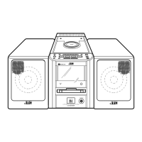
Pin No. Symbol I/O Function
1
2
3
4
5
6
7
8
9
10
11
12
13
14
15
16
17
18
19
20
21
22
23
24
Power GND
Inverted output for CH1
Supply terminal of output stage for CH1
Non-inverted output for CH1
Input for CH1
Input reference voltage
Output reference voltage
Input for CH2
Non-inverted output for CH2
Supply terminal of output stage for CH2
Inverted output for CH2
Power GND
Power GND
Inverted output for CH3
Supply terminal of output stage for CH3
Non-inverted output for CH3
Input for CH3
Supply terminal of small signal GND
Small signal GND
Input for CH4
Non-inverted output for CH4
Supply terminal of output stage for CH4
Inverted output for CH4
Power GND
-
O
-
O
I
-
-
I
O
-
O
-
-
O
-
O
I
-
-
I
O
-
O
-
2.Pin Function
PW GND1
OUT(-)1
PW VCC1
OUT(+)1
VIN1
VRI
VCI
VIN2
OUT(+)2
PW VCC2
OUT(-)2
PW GND2
1
1.Terminal Layout & Block Diagram
TA2092N (IC703) : Power driver IC
2
3
4
5
6
7
8
9
10
11
12
24
23
22
21
20
19
18
17
16
15
14
13
PW GND4
OUT(-)4
PW VCC4
OUT(+)4
VIN4
SVCC1
SGND
VIN3
OUT(+)3
PW VCC3
OUT(-)3
PW GND3
IN1
0
1
0
1
IN2
0
0
1
1
OUT1
H
L
L
OUT2
L
H
L
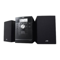
STOP
CW/CCW
CCW/CW
BRAKE
INPUT OUTPUT
IN2 VCC OUT2 NC GND VS OUT1 VREF IN1
123456789
1.Terminal Layout
TA7291S (IC702) : Bridge driver
2.Truth table
MODE
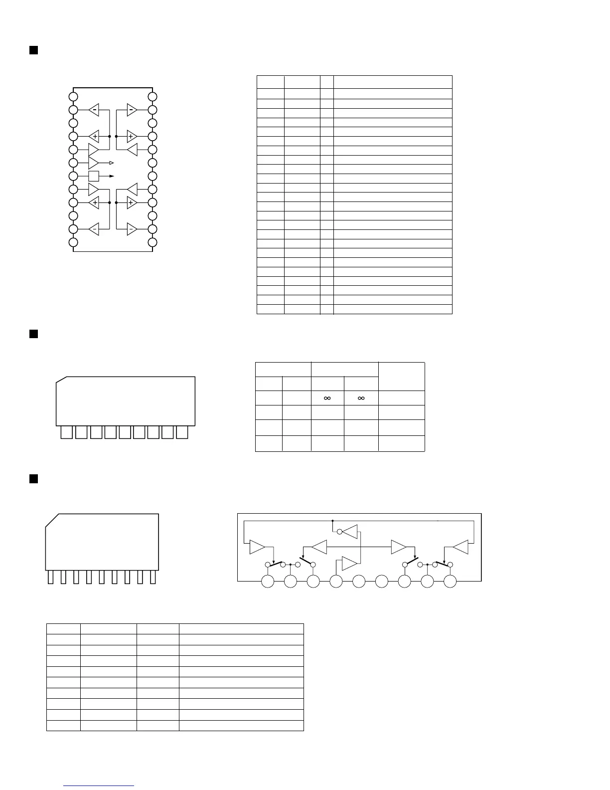
UPC1330(IC201): REC/PB audio head switch
1. Terminal layout
3. Pin function
2. Block diagram
19
123456789
Pin No.
Symbol
I/O
Function
1
2
3
4
5
6
7
8
9
GND
GND
GND
-
-
-
SW
R1
GND
SW
P1
CONT
GND
Vcc
SW
P2
GND
SW
R2
-
-
-
-
-
-
Record SW (Left channel)
Play SW (Left channel)
Record/play control pin
Power supply
Play SW (Right channel)
Record SW (Right channel)
INVERTER
COMPARATOR
 Loading...