Do you have a question about the JVC VN-700 and is the answer not in the manual?
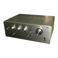
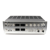
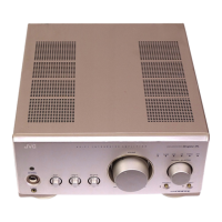
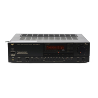
Details on unit type, input/output, and front/rear panel controls.
Information on IHF dynamic power, continuous power, and power bandwidth.
Details on frequency response, S.E.A. controls, and input sensitivity.
Specifications for SUBSONIC, HIGH FILTERS, and Muting.
Power consumption, source, dimensions, and weight of the unit.
Procedure for checking and adjusting power amplifier center voltage and idling current.
Details on packing, included accessories, and used transistors/diodes.
Diagram illustrating the exploded view of the unit's mechanical parts.
List of mechanical parts available for replacement.
Diagram showing the top-view arrangement of internal components.
List of replacement parts corresponding to the top-view diagram.
Detailed list of replacement parts for the front mechanical assembly.
Diagram illustrating the exploded view of the front panel mechanical components.
Diagram showing the exploded view of the unit's rear panel mechanical parts.
List of replacement parts for the rear panel assembly.
Diagram illustrating the exploded view of heat sink and power transistor components.
List of replacement parts for the heat sink and power transistor assembly.
Diagram showing the top layout of the TAE-63B Equalizer Circuit Board.
Diagram showing the bottom layout of the TAE-63B Equalizer Circuit Board.
Information regarding pin connections for specific assemblies.
Catalog of main electronic components available for replacement.
Diagram showing the top layout of the TAC-228A Subsonic/High Filter Circuit Board.
Diagram showing the bottom layout of the TAC-228A Subsonic/High Filter Circuit Board.
Pin connection details for the TAC-228A filter circuit board.
List of main replacement components for the TAC-228A filter circuit board.
Diagram showing the top layout of the TAD-89C Driver Circuit Board.
Diagram showing the bottom layout of the TAD-89C Driver Circuit Board.
Pin connection details for the TAD-89C driver circuit board.
List of main replacement components for the TAD-89C driver circuit board.
Diagram showing the top layout of the TAC-177E Protector Circuit Board.
Diagram showing the bottom layout of the TAC-177E Protector Circuit Board.
Pin connection details for the TAC-177E protector circuit board.
List of main replacement components for the TAC-177E protector circuit board.
Diagram showing the top layout of the TAP-163 Power Supply Circuit Board.
Diagram showing the bottom layout of the TAP-163 Power Supply Circuit Board.
Pin connection details for the TAP-163 power supply circuit board.
List of main replacement components for the TAP-163 power supply circuit board.
Pin connection details for the TAC-229C SEA circuit board.
List of main replacement components for the TAC-229C SEA circuit board.
Diagram showing the top layout of the TAC-229C SEA Circuit Board.
Diagram showing the bottom layout of the TAC-229C SEA Circuit Board.
Guide to resistor part numbers and their corresponding values and types.
Essential checks to perform after completing a repair.
Schematic of the Equalizer (TAE-63B) and Filter (TAC-228A) circuits.
Schematic of the control switches and input/output connections.
Schematic of the Power Supply (TAP-163) and Protector (TAC-177E) circuits.
Schematics for the TAC-228A Filter and TAD-89C Driver circuit boards.
Schematics showing transistor (X501-X505, X402-X408) and relay connections.
Schematic details for SELECT, TAPE MONITOR, and MODE switches.
Schematic for POWER, MUTING, LOUDNESS, SPEAKERS, and FILTER controls.
Detailed schematic of the TAD-89C driver board and transistor interconnections.
Schematic for the voltage selector plug and fuse components.