XV-M565BK/M567GD
1-9
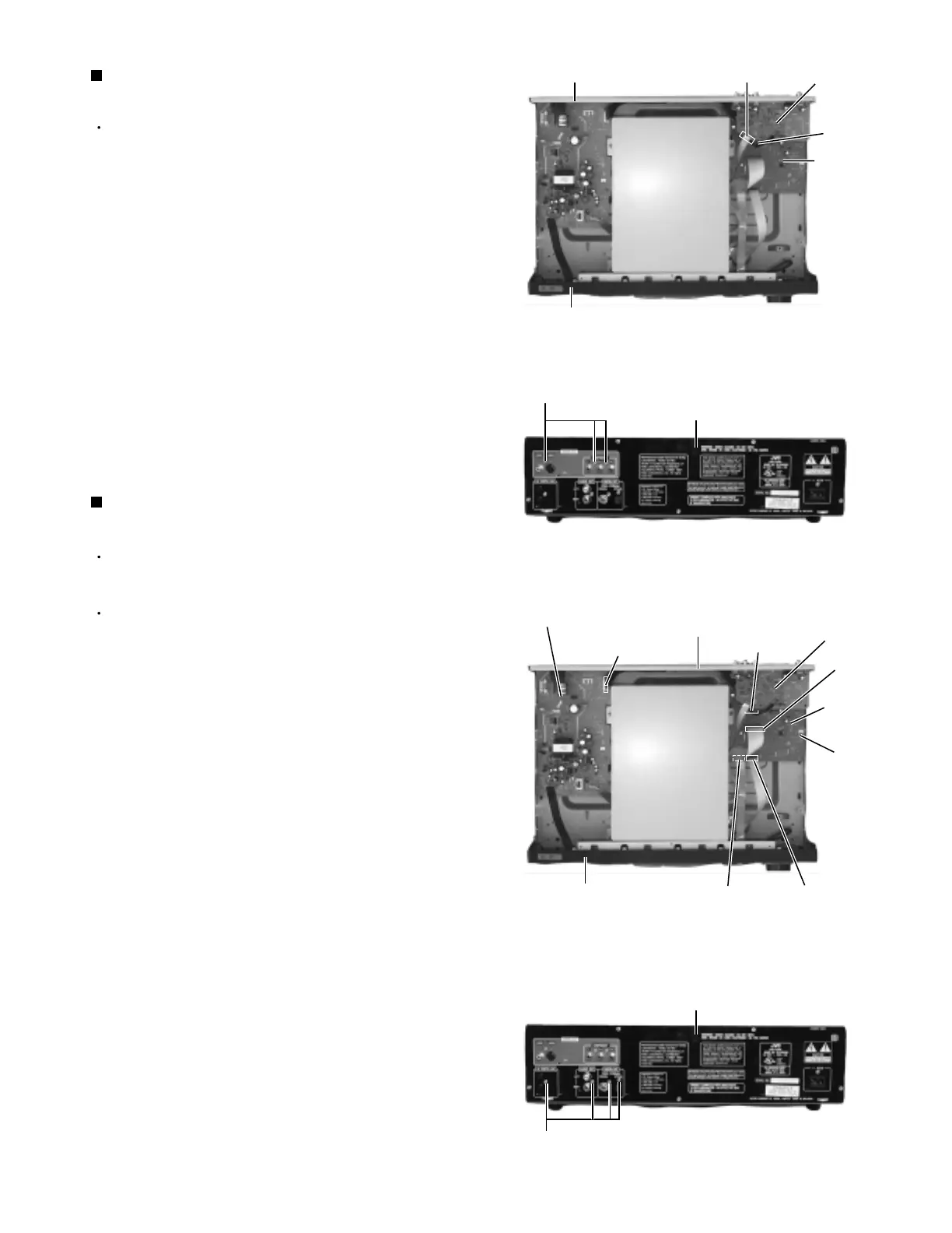
Prior to performing the following procedure, remove
the top cover.
Disconnect the card wire from connector CN601 on
the video board (The card wire is extending from the
DVD changer mechanism assembly).
Disconnect the harness from connector CN704 on
the system control board (The harness is extending
from the video board).
Remove the three screws D attaching the video
board on the rear panel. Pull out the video board
from the rear panel.
1.
2.
3.
Removing the Video board
(See Fig.11 and 12)
Prior to performing the following procedure, remove
the top cover.
The audio board can be removed even if the video
board is attached.
Disconnect the card wire from connector CN703 on
the system control board (The card wire is extending
from the front panel assembly).
Disconnect the card wire from connector CN701 and
CN702 on the audio board (The card wires are
extending from the DVD changer mechanism
assembly).
Disconnect the harness from connector CN704 on
the system control board (The harness is extending
from the video board).
Disconnect the harness from connector CN951 and
CN952 on the power supply board (The harness is
extending from the system control board).
Remove the screw H attaching the system control
board.
Remove the five screws D attaching the system
control board on the rear panel. Pull out the system
control board toward the front.
1.
2.
3.
4.
5.
6.
Removing the System control board
(See Fig.13 and 14)
Front panel assembly
Rear panel
Video board
System
control
board
CN601
CN704
Shield case
Shield case
Fig.11
Fig.12
Fig.13
Fig.14
Rear panel
Rear panel
D
Front panel assembly
Rear panel
Video board
System
control
board
CN704
CN701
CN703 CN702
H
Power supply board
CN951
CN952
D
 Loading...